
Water hammer, also known as hydraulic surge, is a pressure wave that happens in fluid systems when fluid in motion abruptly stops or changes velocity. This phenomenon can lead to various issues, including noise, vibrations, burst pipes, valve failures, or even structural damage.
This article tackles water hammer calculations, its underlying principles, and methods to prevent and mitigate its effects.
Water Hammer Calculation
When a high fluid flow velocity changes abruptly in a confined system, like pipes, it creates a pressure surge known as water hammer. This surge generates sonic waves that cause a hammering noise in the pipes, hence the name.
The developed pressure can exceed the normal operating pressure several times, leading to potential damage to pipes, fittings, valves, and connected equipment. This damage may result in leaks and reduce the system’s lifespan. In extreme cases, it can even cause bursting of pipes or damage to the pump system.

Elevate Your Engineering With Excel
Advance in Excel with engineering-focused training that equips you with the skills to streamline projects and accelerate your career.
Water hammer occurs most commonly due to the immature or abrupt closing of a valve. However, it can also be triggered by a power outage, sudden stoppage of a pump, changes in tank levels, entrained air, temperature fluctuations, and other factors. It is important to remember that despite the name, this phenomenon can happen in any type of fluid system, not exclusively in water.
Water hammer is an important issue especially in fluid systems where the flow of water must be rapidly varied. For example, in hydroelectric plants where the flow of water is rapidly varied in proportion to the load changes in the turbine.
To understand how water hammer occurs, consider a valve in a pipe.
When the valve is suddenly closed, the fluid layer near the valve gets compressed by the incoming flow, resulting in a higher local pressure. At the same time, the pipe wall surrounding the compressed fluid is stretched due to the excess pressure. This process recurs for each successive layer of incoming fluid, resulting in the propagation of increased pressure along the pipeline in the form of sonic waves, traveling away from the valve.
Velocity Of Pressure Wave Or Celerity Formula
The velocity at which the pressure propagates along the pipe is called the celerity. In general, the celerity of a pressure wave can be calculated using the following formula:
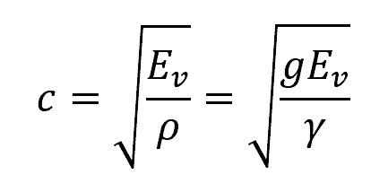
Where:
- c = celerity or velocity of pressure wave [m/s]
- Ev = bulk modulus of elasticity of the fluid [N/m2]
- ρ = density of the fluid [kg/m3]
- g = gravitational acceleration [9.81 m/s2]
- γ = specific weight of the fluid [N/m3]
For water, the typical value of the bulk modulus of elasticity is 2.07×10⁶ kN/m2, resulting in a celerity equal to 1440 m/s at standard conditions.
The above formula does not consider the pipe material’s elasticity. However, in reality, the elasticity of the pipe material reduces celerity due to the stretching of the pipe wall. In this case, the bulk modulus is replaced by the joint modulus of elasticity, which can be obtained using the following formula:
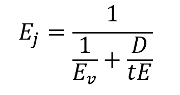
Where:
- Ej = joint modulus of the fluid and pipe material [N/m2]
- D = diameter of the pipe [m]
- t = wall thickness of the pipe [m]
- E = modulus of elasticity of the pipe material [N/m2]
Consequently, the formula for the celerity of a pressure wave in an elastic pipe can be written as:
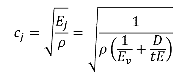
Where:
- cj = celerity in an elastic pipe [m/s]
The table below shows the modulus of elasticity of common pipe materials.
Water Hammer Pressure
After a brief period, the pressure wave from the valve will reach the pipe inlet at point M. At this point, the entire fluid along the pipe will come to rest, but at an elevated pressure throughout.
As the pressure wave travels from the valve to the pipe inlet, there will be a transient hydraulic grade line, running parallel to the original steady-flow grade line, but positioned higher by a height equal to ΔP/γ. ΔP represents the water hammer pressure.
The formula for calculating the water hammer pressure depends on how fast the fluid momentum changes; in this case, how fast the valve is closed.
Juokowsky Formula For Water Hammer Pressure
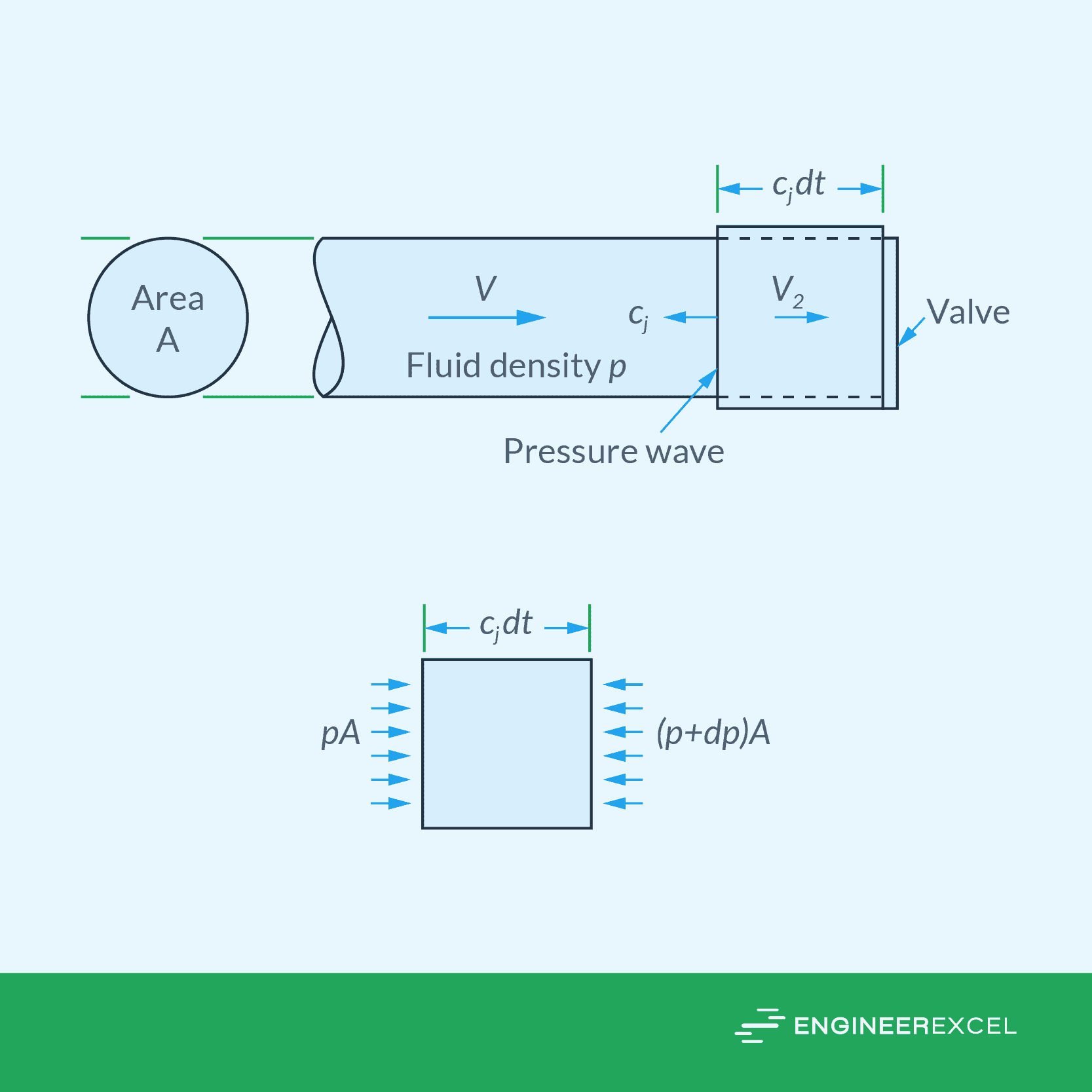
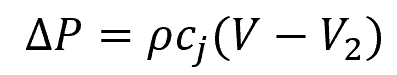
When a valve is closed rapidly, but not necessarily completely, a pressure wave travels upstream and a portion of the fluid is decelerated, as shown in the diagram above. In this case, the water hammer pressure can be calculated using the Juokowsky formula:
Where:
- ΔP = water hammer pressure for rapid closure [Pa]
- V = initial velocity of the incoming fluid [m/s]
- V2 = decelerated final velocity of the fluid [m/s]
If the valve is completely closed, the final velocity V2 reduces to zero, and the formula for water hammer pressure becomes:
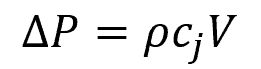
Notice that the magnitude of water hammer pressure is not affected by the length of the pipe. Instead, it solely depends on the celerity of the pressure wave and the change in the velocity of the fluid.
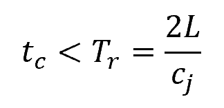
It is also important to note that the above formula only applies to rapid valve closure. A valve closure is considered rapid if the time taken to close the valve satisfies the following condition:
Where:
- tc = time taken to close the valve [s]
- Tr = time for a complete round trip of the pressure wave along the pipe’s length [s]
- L = length of the pipe [m]
Water Hammer Pressure For Gradual Closure
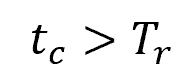
On the other hand, a valve closure is considered slow or gradual if the time taken to close the valve satisfies the following condition:
In this case, the water hammer pressure is reduced because the wave of pressure unloading will reach the valve prior to the valve’s full closure. This effectively prevents any additional pressure buildup. The maximum water hammer pressure in this situation can be calculated using the following formula:
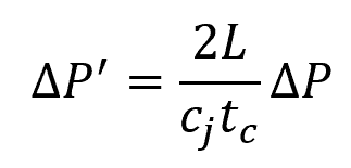
Where:
- ΔP’ = water hammer pressure for gradual closure [Pa]
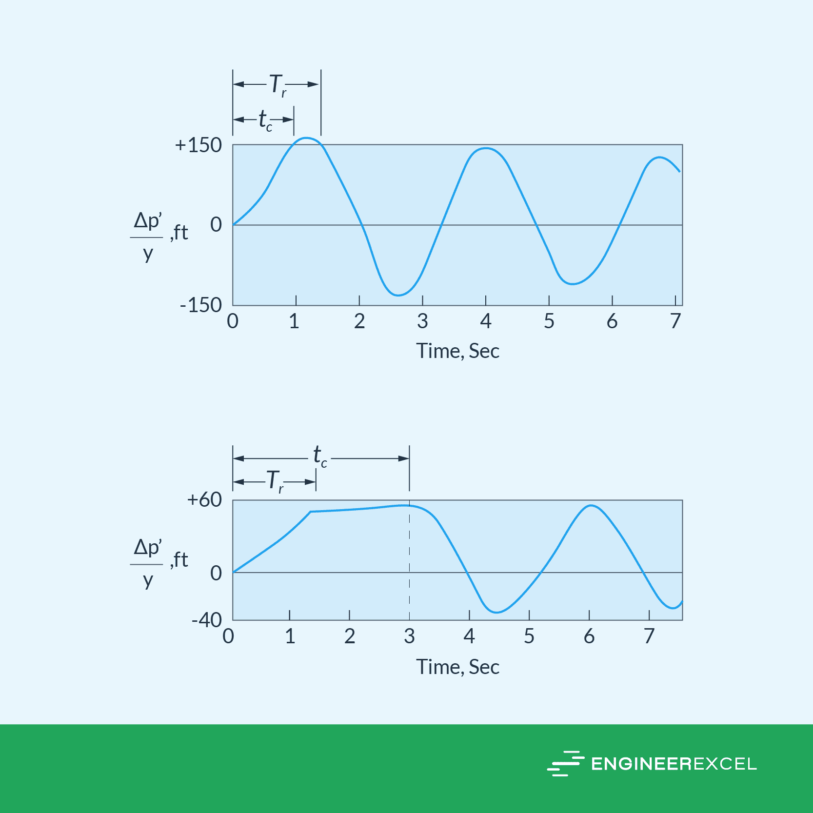
The following graphs depict the pressure change at the valve experiencing water hammer over time. The left graph illustrates a rapid complete valve closure with tc=1, while the right graph demonstrates a gradual complete valve closure with tc=3.
Water Hammer Analysis Using Computer Techniques
In reality, the pressure changes that occur during water hammer are complex and requires a detailed, step-by-step analysis. A more accurate way to analyze water hammer is by applying Newton’s second law of motion and continuity principles, resulting in two nonlinear partial differential equations. These equations have two unknowns: volume and head, which are functions of both position and time, as shown in the following equations.
Equation of motion:
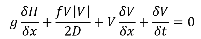
Equation of continuity:
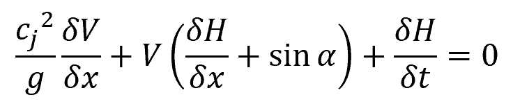
Where:
- H = piezometric head at the centerline of the pipeline at location x and time t [m]
- V = average velocity of flow [m/s]
- D = pipe diameter [m]
- f = Darcy-Weisbach friction factor [unitless]
- x = distance along the centerline of the pipe [m]
- α = angle between the horizontal and the centerline of the pipe [rad]
- t = time [s]
The equations above are a pair of partial differential equations that relate two dependent variables, H and V, with respect to x and t. Although there is no general solution for these equations, they can be solved using the method of characteristics. This involves turning the partial differential equations into ordinary differential equations, whose two unknowns can be solved simultaneously using a finite difference solution.
To do this, the pipe is divided into a number of incremental lengths. Each node is assigned an initial value and the boundary conditions are prescribed at both ends of the pipe. The great thing about using a computerized solution is that it can handle complex boundary conditions that can vary with other variables in the system.
Reduction And Mitigation Of Water Hammer Pressure
There are several methods available to reduce water hammer pressure and mitigate its effects on a system. The general approach is to minimize the occurrence of transient conditions during the system’s design phase and incorporate transient control devices in the system. These devices serve to decrease wave speed, reduce fluctuations in fluid velocity, and constrain local pressure variations.
For instance, soft starters can be used to ensure that the pump motor accelerates gradually, rather than reach full speed instantly. This controlled acceleration can help avoid sudden changes in flow rates that may lead to water hammer.
Similarly, integrating flywheels with pumps can help smoothen out fluctuations in pump speed caused by variations in the driving force, such as changes in the power source or variations in the fluid being pumped. This can result in a more stable and consistent pump operation, reducing wear and tear on pump components and extending their lifespan.
Along the pipeline, the implementation of slow-closing valves can smoothly regulate flow and limit abrupt shifts in fluid momentum. Automatic relief valves can also be used to release fluid if pressure surpasses a predefined threshold. Similarly, water hammer arrestors and surge tanks, which contain compressed cushions of air, can act as buffers to absorb pressure changes.