
In
Fundamentals of Boundary Layers
The boundary layer in pipe flow is essential to understanding fluid dynamics and heat transfer phenomena within pipelines.
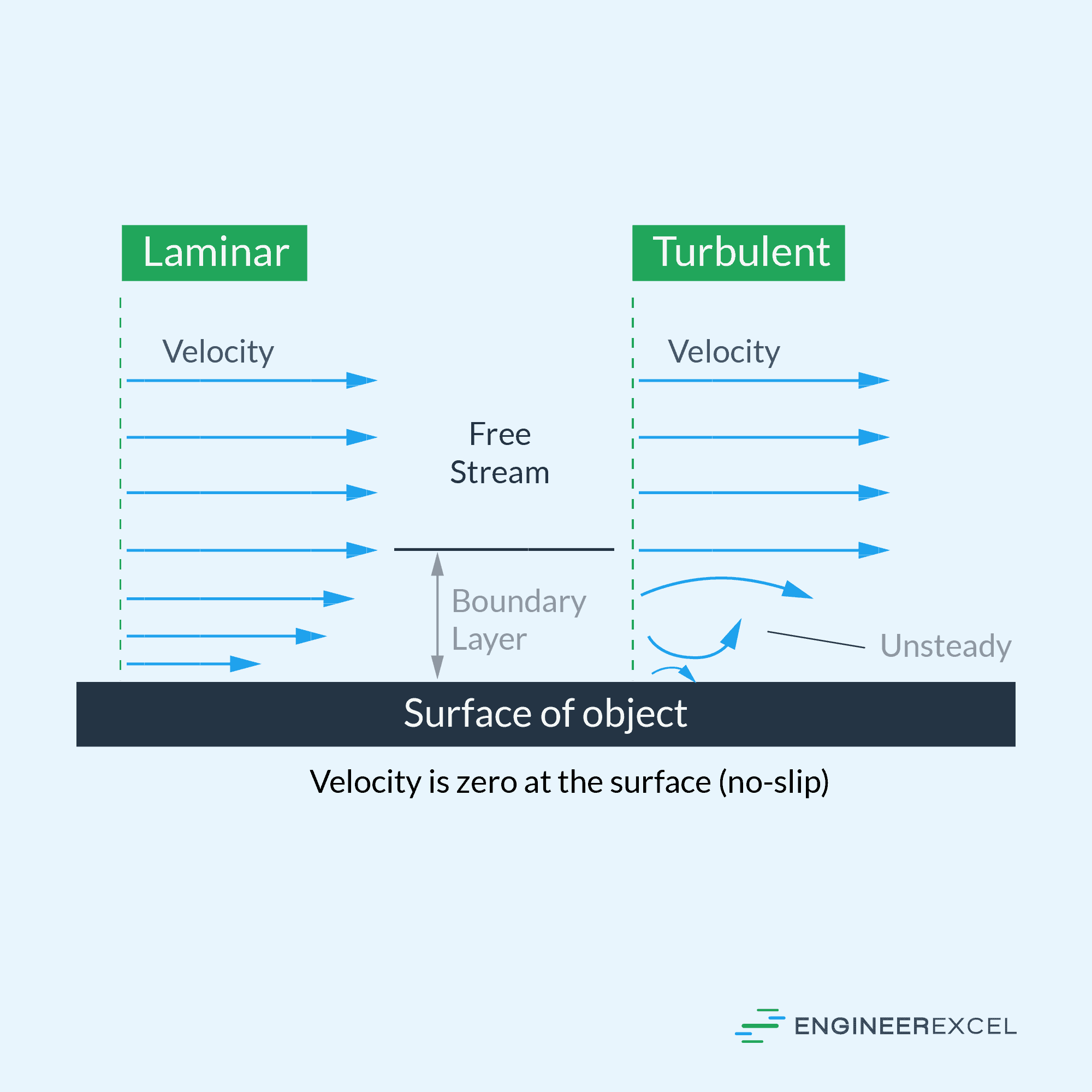
The boundary layer is a thin fluid layer near a solid object’s surface, such as a pipe wall, where viscous forces dominate the flow behavior. It can be classified primarily into two types:
- Laminar boundary layer
- Turbulent boundary layer

Elevate Your Engineering With Excel
Advance in Excel with engineering-focused training that equips you with the skills to streamline projects and accelerate your career.
A laminar boundary layer is characterized by smooth and orderly fluid flow, while a turbulent boundary layer exhibits chaotic and more random flow patterns.
The transition from laminar to turbulent flow is mainly determined by the Reynolds number, a dimensionless value calculated as:
Re = ρVD/μ
Where Re is the Reynolds number, ρ is the fluid density, V is the flow velocity, D is the pipe diameter, and μ is the fluid viscosity.
The critical Reynolds number for pipe flow is typically around 2,000. Flows with Reynolds numbers below this value are generally laminar, while those above are turbulent.
In a boundary layer, the fluid velocity transitions from zero at the wall to the free-stream velocity away from the wall. Engineers often define this region by defining boundary layer thickness (denoted as δ). Inside the boundary layer, essential parameters like shear stress, pressure distribution, and velocity profiles can be determined using governing equations, such as:
- Continuity Equation
- Momentum Equations (Navier-Stokes Equations)
- Energy Equation
Solving these equations for specific pipe flow scenarios can help predict fluid behavior and inform design decisions in various engineering applications, such as piping systems, heat exchangers, etc.
Characteristics of Boundary Layers
The boundary layer development happens close to the pipe walls, where the fluid interacts with the solid surface, leading to a velocity gradient. The boundary layer thickness increases with the distance along the pipe. It comprises two primary regions:
- The laminar sublayer: A thin layer adjacent to the wall with smooth and linear fluid flow.
- The turbulent region: An outer layer characterized by turbulent, chaotic flow regimes.
The boundary layer thickness (δ) depends on the Reynolds number (Re) and the pipe diameter (D). Generally, the thicker the boundary layer, the greater the resistance to fluid flow and the higher the energy losses due to friction.
The wall shear stress (τ) is a significant factor in the boundary layer, leading to pressure drop development in pipe flow. The wall shear stress is directly related to the fluid density (ρ), velocity (u), and kinematic viscosity (ν).
The boundary layer velocity profile and the wall shear stress can be described by different formulas, depending on whether the flow is laminar or turbulent. The Blasius solution is typically used for laminar flow (Re < 2300). For turbulent flow (Re > 4000), the smooth-wall or rough-wall law of the wall equations are employed.
The boundary layer is crucial in understanding energy losses and pressure drops in pipe flow. In addition, the above characteristics help determine how different parameters influence the interaction between fluid and pipe walls, improving our understanding of fluid dynamics in pipes.
Types of Pipe Flow
Both laminar and turbulent flow have distinct characteristics and can be further explained through critical parameters.
Laminar Flow: When fluid flows smoothly and consistently in parallel layers, it is considered to be in laminar flow. This flow type is typically observed in pipes with low velocities and relatively small diameters. In this regime, the fluid’s motion is predictable, and viscous forces mainly drive the flow. The Reynolds number (Re) is a significant dimensionless parameter to determine the flow regime. If Re is less than 2,000, the flow is considered laminar.
| Parameter | Description |
| Reynolds Number | < 2,000 |
| Flow Characteristics | Smooth, Viscous Forces dominate |
Turbulent Flow: Turbulent flow occurs when fluid moves chaotically with irregular fluctuations in velocity and pressure. It is typically observed in pipes with large diameters and high fluid velocities. Unlike laminar flow, which is predictable, the behavior of turbulent flow is more complex, and both viscous and inertial forces drive the flow. The flow is considered turbulent if the Reynolds number is greater than 4,000.
| Parameter | Description |
| Reynolds Number | > 4,000 |
| Flow Characteristics | Chaotic, Viscous and Inertial Forces |
It is important to note that there is a range of Reynolds numbers (2,000 to 4,000) between these two regimes, known as the transitional flow regime, where the flow can exhibit characteristics of both laminar and turbulent flows.
Boundary Layer Development in Pipe Flow
In pipe flow, boundary layer development is crucial in understanding and predicting fluid behavior. We will discuss the development of the boundary layer and its key characteristics in this section.
The boundary layer is a thin region of fluid close to the pipe wall, where viscous forces significantly impact the flow. This region is characterized by a velocity gradient, where the fluid velocity changes rapidly as it approaches the pipe wall. As the fluid travels through the pipe, the boundary layer thickness and velocity profile change with the flow conditions.
Boundary layer development in pipe flow can be divided into three main stages:
- Laminar (or viscous) sublayer
- Buffer layer
- Turbulent core layer
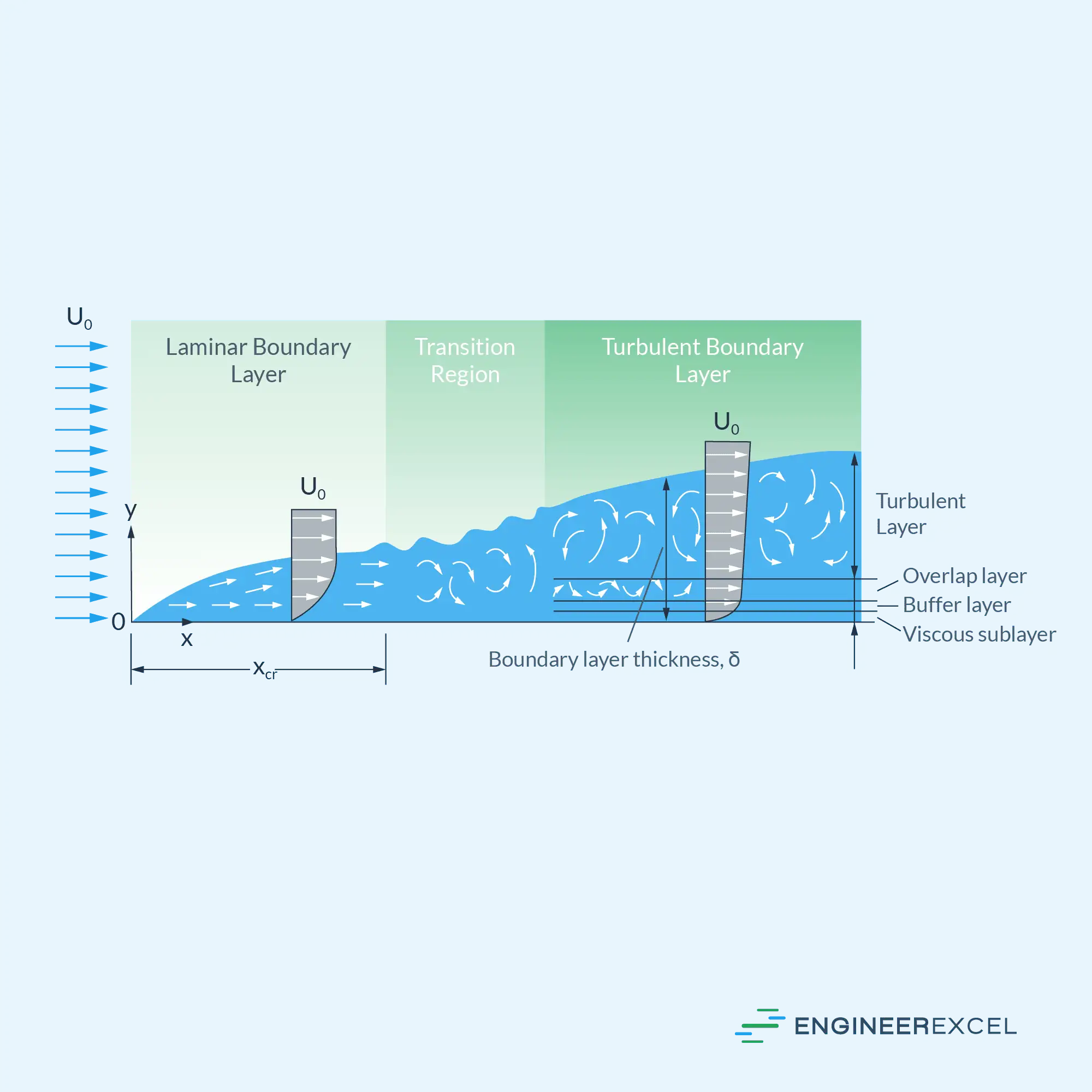
The laminar sublayer is the region closest to the pipe wall, where flow behaves stably and linearly. Here, viscous forces dominate, and velocities vary linearly with distance from the wall.
Adjacent to the laminar sublayer, the buffer layer forms as the boundary layer thickens. Here, turbulent fluctuations in velocity become more significant, and the flow transitions between laminar and turbulent characteristics.
The turbulent core dominates the remaining volume of the pipe, where the flow is primarily turbulent and fluid motion is chaotic. In this region, inertial forces overcome viscous forces, resulting in the typical logarithmic velocity profile of fully-developed turbulent pipe flow.
Boundary layer development profoundly impacts pressure losses, heat transfer, and other phenomena in pipe flow. The following table shows how various factors change as the boundary layer develops:
| Stage | Function | Thickness |
| 1. Laminar sublayer | Linear velocity profile | Small |
| 2. Buffer layer | Transitional velocity profile | Intermediate |
| 3. Turbulent core | Logarithmic velocity profile | Large |
Effects of Boundary Layer Thickness
The boundary layer thickness in pipe flow significantly impacts various aspects of fluid flow, such as velocity distribution, pressure drop, and heat transfer. This section will discuss the effects of varying boundary layer thickness and its implications on pipe flow.
As the fluid flows through a pipe, the boundary layer thickness increases from the pipe’s entrance to a certain point called the hydrodynamic entrance length. This is where the boundary layer growth saturates and merges to form a fully developed flow. A thicker boundary layer reduces the velocity gradient near the pipe wall, which can affect the overall flow behavior.
A change in boundary layer thickness can influence the pressure drop along the pipe. The pressure drop primarily depends on the flow rate and the friction factor, which in turn is influenced by the Reynolds number and the relative roughness of the pipe surface. A thicker boundary layer often leads to:
- A reduction in turbulent intensity near the pipe wall, leading to decreased friction losses.
- An increased likelihood of flow separation in adverse pressure gradient regions may cause higher pressure drop.
Furthermore, the boundary layer thickness is crucial in heat transfer between the fluid and the pipe wall. The thermal boundary layer forms due to viscous and thermal effects, and its thickness determines the temperature gradient near the pipe surface. A thicker boundary layer generally indicates a lower heat transfer rate, which can compromise the heat exchange efficiency in applications such as heat exchangers and cooling systems.
Measurement Techniques
The boundary layer in pipe flow is essential for analyzing fluid dynamics and engineering applications. Various measurement techniques are employed to obtain accurate data on velocity profiles, pressure distribution, and turbulence characteristics. Below are some of the methods used for studying boundary layers in pipe flow:
1. Pitot-Static Tube
A widely used technique for measuring local fluid velocities, the pitot-static tube measures the difference between static and dynamic pressures. This enables the determination of the velocity profile in the boundary layer. The device consists of a narrow tube with open ends aligned with and opposing the flow direction. The boundary layer properties can be analyzed by relating the pressure difference to fluid velocity.
2. Laser Doppler Anemometry (LDA)
LDA is a non-intrusive technique that uses a laser doppler system to measure local fluid velocities. The flow is seeded with small, light-scattering particles illuminated by a laser beam. The scattered light’s frequency shift is proportional to the fluid velocity. As a result, LDA provides highly accurate flow velocity measurements and allows for investigating turbulent fluctuations within the boundary layer.
3. Particle Image Velocimetry (PIV)
Like LDA, PIV is a non-intrusive optical measurement technique. However, PIV measures the apparent shift of particle patterns within the flow instead of scattered light frequency. Using a high-speed camera and a pulsed laser light sheet, thousands of particles’ displacement is captured quickly, enabling calculating velocity profiles and turbulence properties within the boundary layer.
4. Hot-Wire Anemometry (HWA)
HWA relies on a thin, heated wire placed in the flow to measure fluid velocities. Based on heat transfer principles, as the flow passes over the heated wire, it convects heat away, causing the wire’s temperature and resistance to change. By correlating the resistance change to the velocity, HWA provides high-resolution measurements of local velocities and turbulence properties in the boundary layer.
These measurement techniques offer different advantages and limitations, and the choice of method depends on the specific application, desired accuracy, and experimental setup. Nevertheless, researchers can gain valuable insights into the pipe flow’s boundary layer and improve engineering designs by employing appropriate techniques.
Practical Applications and Industry Examples
In this section, we will explore some practical applications, and industry examples where understanding the boundary layer in pipe flow is crucial.
Boundary layer characteristics in pipe flows play an essential role in various industries, including fluid transport systems, power generation, and chemical and petrochemical processes. Therefore, optimizing pipe flow management ensures efficiency and performance in these sectors.
In the oil and gas industry, controlling the pipeline flow rate is crucial to maintain the required pressure levels and avoid issues related to corrosion, erosion, and cavitation. Comprehending boundary layer behavior enables engineers to design pipelines that minimize the energy loss associated with turbulence and flow separation.
Water treatment plants also rely on accurate boundary prediction estimations. Ensuring proper flow management within these facilities helps maintain system efficiency, prolong the service life of equipment, and prevent potential contamination within the system.
Another application area is power generation, such as nuclear and thermal power plants. A proper understanding of the boundary layer in these facilities helps engineers design efficient heat exchange systems, manage coolant flow through pipes, and optimize the overall system for maximum energy production.
The following table lists some industries and related applications where a solid understanding of boundary layers in pipe flow is indispensable:
| Industry | Application |
| Oil and Gas | Pipeline transportation |
| Water Treatment | Fluid management and contamination prevention |
| Power Generation | Heat exchange systems and coolant flow |
| Chemical and Petrochemical | Flow management and process optimization |
In conclusion, the boundary layer in pipe flow significantly impacts various industries and practical applications. Proper understanding and management of flow behavior lead to increased efficiency and performance in critical systems.