
An orifice plate is a thin plate with a hole, typically positioned within a pipe to restrict flow. It finds extensive application in the measurement and control of liquid or gas flow within pipelines. This article delves into the concept of orifice plates, the different ways they can be configured, and the calculations involved in their practical application.
Orifice Plate
An orifice plate is a thin plate with a hole, referred to as an orifice, drilled in it. It can be used as a restriction plate to limit flow or reduce pressure. However, it is more commonly used as the primary component of orifice meters— a type of inferential flow meter that indirectly measures flow rate based on the pressure drop developed across the plate.
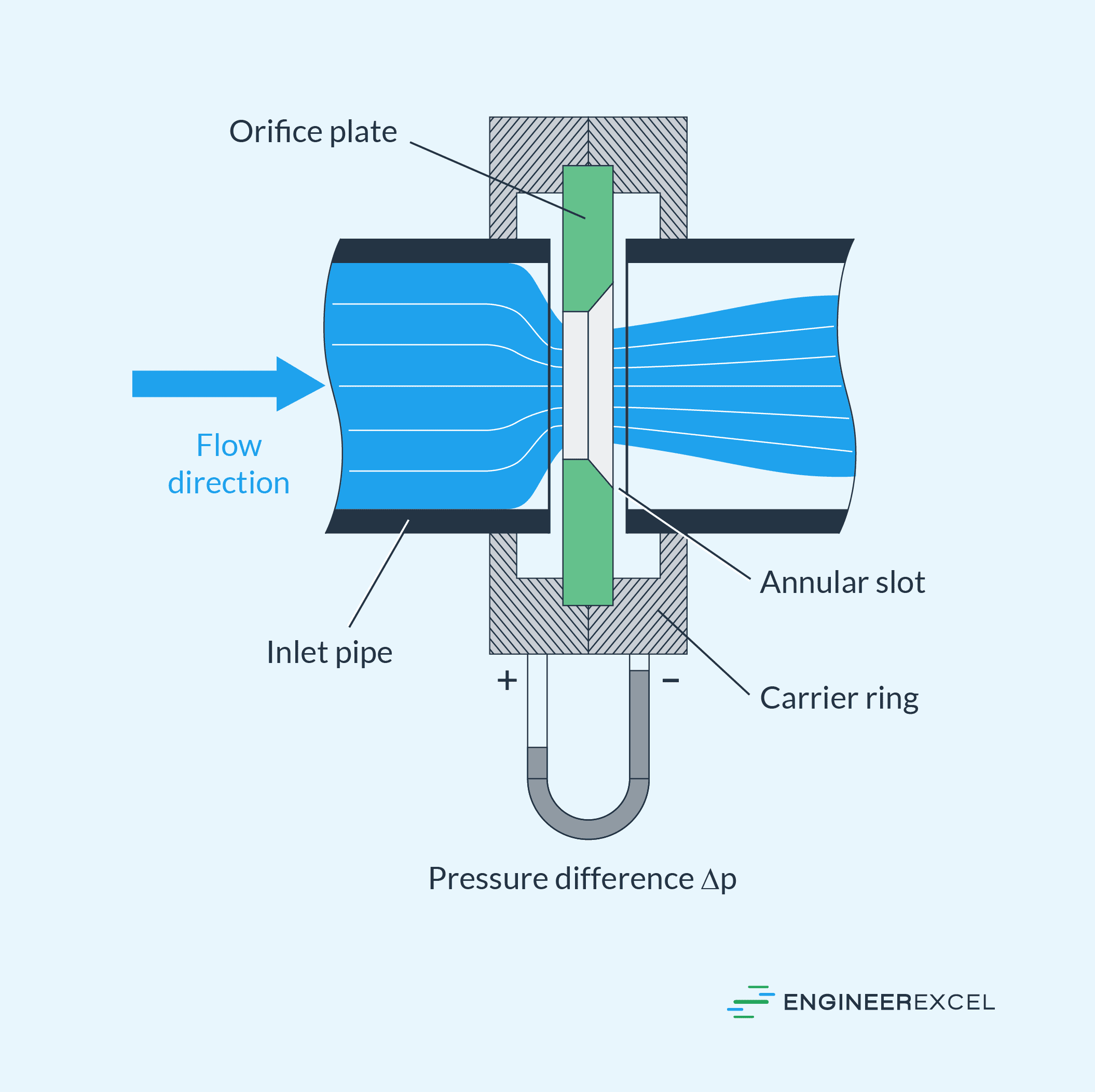
The working principle of an orifice plate is based on Bernoulli’s principle. In order to measure the flow, the orifice plate is inserted into a pipe or flowline. As the fluid flows through the orifice, its velocity increases, causing a decrease in pressure.

Elevate Your Engineering With Excel
Advance in Excel with engineering-focused training that equips you with the skills to streamline projects and accelerate your career.
By measuring the pressure difference before and after the orifice, the fluid velocity can be determined using Bernoulli’s equation. In turn, this velocity can be used to calculate the flow rate. These calculations are normally based on empirical data.
Orifice plates find widespread use in various industrial applications for flow measurement, including oil and gas, chemical processing, water treatment, and HVAC systems. They offer a simple and cost-effective solution for measuring flow rates of liquids, gases, and steam in pipes.
However, it is important to note that orifice plates are only suitable for flow measurement when the fluid is single-phase, homogeneous, and with a continuous and well-developed flow profile. Compared to other flowmeters, orifice plates also introduce a significant pressure drop in the system, which may not be suitable for low-pressure and viscous fluid systems.
Types Of Orifice Plates
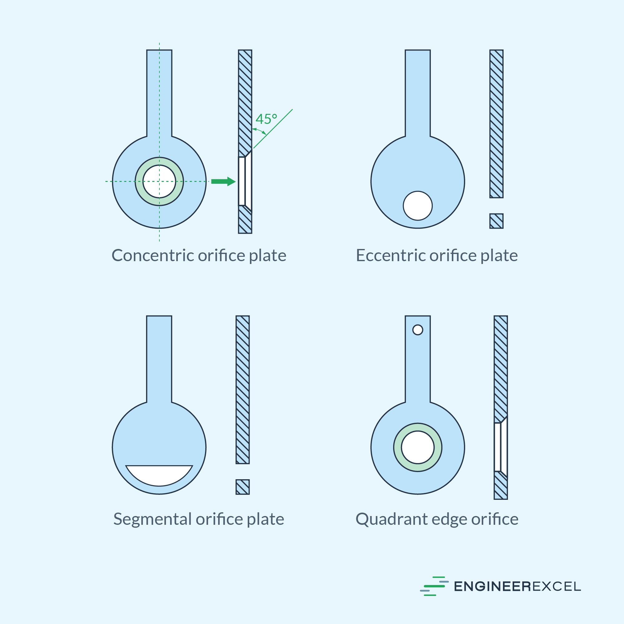
Orifice plates can be classified into four main types based on their bore configuration: concentric, eccentric, segmental, and quadrant edge. Each type is specifically designed to accommodate different applications and flow conditions.
Concentric Orifice Plate
The concentric orifice plate is the most common type. It is named so because the circular orifice is centrally located, and the plate thickness is uniform around the orifice, resulting in a concentric design. This design ensures symmetrical flow around the orifice, making it suitable for general flow measurement applications.
Standard concentric plates are commonly manufactured using stainless steel and have a thickness within the range of 1/8 to ½ inches. The actual thickness depends on the beta ratio, which represents the ratio between the orifice diameter and the internal diameter of the pipeline.
To reduce friction and resistance as the fluid flows through the restriction, the bore of the plate is typically beveled at a 45-degree angle, with the sharp or unbeveled edge facing the incoming flow. As a general practice, unless specified otherwise, the plates are beveled to a dimension of 1/50 of the internal diameter of the pipeline or 1/8 of the orifice bore, whichever is lower.
Eccentric Orifice Plate
The eccentric orifice plate is different from the concentric type in that the position of its orifice is located off-center, aligned tangentially with the inner wall of the pipe. This configuration is effective when measuring fluids that contain small amounts of suspended solids, slurries, or viscous materials.
Since the opening is located at the bottom of the pipe, impurities can pass through without accumulating on the orifice plate. This minimizes the risk of blockage or damage to the plate.
However, due to its off-center positioning, the eccentric orifice plate creates a vena contracta— the point of maximum fluid velocity— that differs from that of concentric plates. As a result, the potential measurement error with an eccentric plate can be up to five times greater compared to a concentric plate.
Unlike concentric plates, which feature beveled edges, eccentric plates typically have straight edges.
Segmental Orifice Plate
Similar to eccentric orifice plates, segmental orifice plates are employed for fluids that contain small amounts of suspended solids, slurries, or viscous materials. However, unlike eccentric orifice plates, which feature an offset circular bore, segmental orifice plates have a segmented opening shaped like a partially opened gate valve. This opening can be positioned at the top or bottom of the pipe.
Industries such as sewage treatment, steel production, paper manufacturing, and petrochemicals utilize these plates.
Quadrant Edge Orifice Plate
The quadrant edge orifice plate shares similarities with concentric orifice plates, as it also features a concentric opening. However, unlike the sharp edge of concentric plates, the quadrant edge orifice plate has a rounded edge whose radius is a function of the orifice diameter.
This design is specifically employed when measuring viscous fluids. Tests have demonstrated that this type of plate maintains a consistent coefficient of discharge, particularly in the low Reynolds number or viscous flow region.
In addition, quadrant edge orifice plates are utilized when cavitation is a concern. The rounded edge serves to minimize the erosive effects of suspended particles passing through the orifice, reducing wear and extending the plate’s lifespan.
Measuring Flow Using Orifice Plate
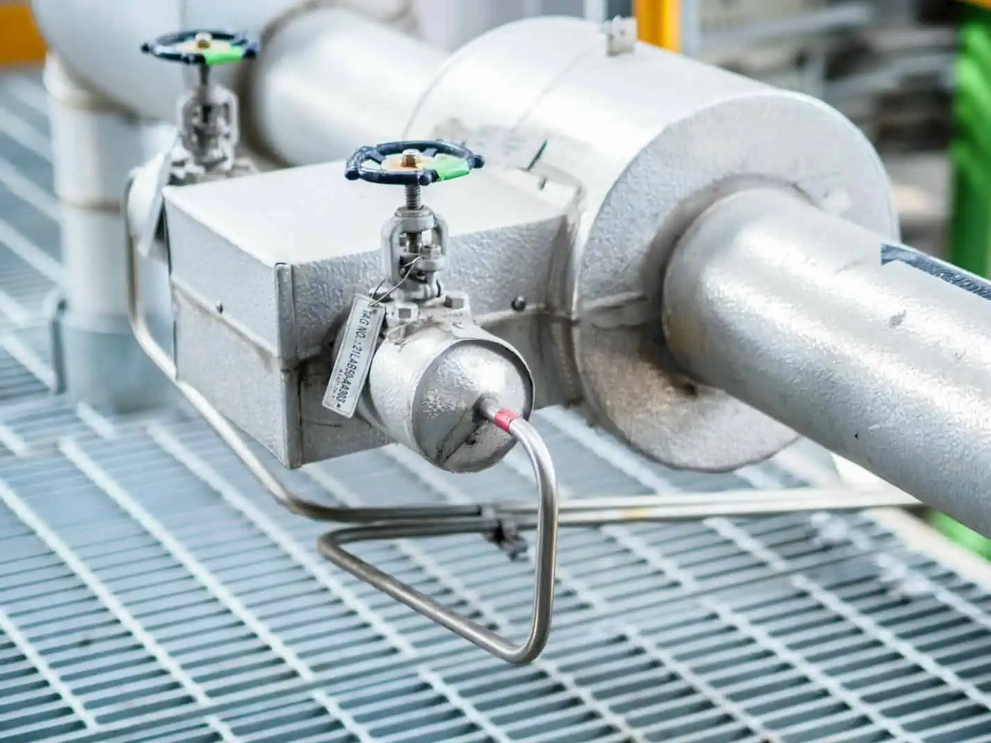
To accurately measure flow rate using an orifice plate, it is crucial to install the plate in straight sections of the pipe, avoiding any interference from fittings or valves. This ensures that the flow patterns remain undisturbed.
Once the orifice plate is installed, the next step is to measure the pressure differential while the fluid passes through the orifice. This is normally done using pressure transmitters that are strategically placed before and after the orifice.
Note that there are various standards on the configuration of pressure taps. The ideal scenario involves the upstream tap detecting fluid pressure at the point of minimum velocity, while the downstream tap captures pressure at the vena contracta, where the velocity is at its maximum. However, achieving this ideal is challenging in reality.
The most common pressure tap configuration, especially in large installations, is using flange taps. These taps offer pre-drilled tap holes in the flanges, eliminating the need for post-installation drilling, which can be labor-intensive. These taps are typically positioned one inch away from both the upstream and downstream faces of the orifice plate.
Once the pressure differential is measured, the flow rate can be calculated based on empirical data.
Formula For Incompressible Flow Through An Orifice Plate
Theoretically, the formula for calculating the volumetric flow rate of an incompressible fluid flowing through an orifice plate can be expressed as follows:
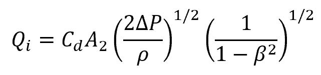
Where:
- Qi = volumetric flow rate of an incompressible flow [m3/s]
- A2 = cross-sectional area of the flow at the vena contracta [m2]
- Cd = orifice plate coefficient of discharge [unitless]
- ΔP = pressure differential across the orifice [Pa]
- ρ = fluid density [kg/m3]
- β = beta ratio, ratio between the diameter of the orifice and the pipe internal diameter [unitless]
However, predicting the actual flow profile at the vena contracta is challenging, making the effective value of A2 uncertain. Hence, in practice, the equation above is modified by utilizing the orifice area instead of the area of the flow at the vena contracta. Additionally, the coefficient of discharge, Cd, is substituted with a new flow coefficient, Cf.
The simplified formula for the volumetric flow rate becomes:
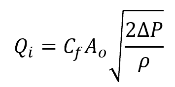
Where:
- Ao = cross-sectional area of the orifice [m2]
- Cf = orifice plate flow coefficient [unitless]
The flow coefficient is determined through experiments and can be found in various reference books. Its value is dependent on the size and configuration of the orifice, the beta ratio, and the Reynolds number of the fluid flow. In most types of orifice plates, the flow coefficient typically falls within the range of 0.6 to 0.9.
Formula For Compressible Flow Through An Orifice Plate
For compressible fluids, like gas, the calculation becomes much more complex and the equation needs to be modified to account for the effects of temperature, specific gravity, and gas expansion, among others. The general formula for calculating the volumetric flow rate of a compressible fluid flowing through an orifice plate can be expressed as follows:
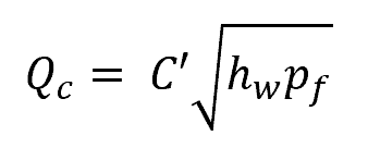
Where:
- Qc = volumetric flow rate of a compressible flow [scf/hr]
- C’ = orifice flow coefficient for compressible fluids [unitless]
- hw = pressure differential across the orifice [inches of water]
- pf = upstream pressure [psia]
The orifice flow coefficient for compressible fluids is the product of various factors as follows:
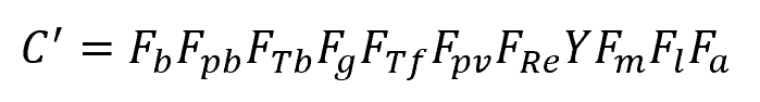
Where:
- Fb = basic orifice factor [unitless]
- Fpb = pressure base factor [unitless]
- FTb = temperature base factor [unitless]
- Fg = specific gravity factor [unitless]
- FTf = flowing temperature factor [unitless]
- Fpv = gas deviation factor [unitless]
- FRe =Reynolds number factor [unitless]
- Y = expansion factor [unitless]
- Fm = manometer factor [unitless]
- Fl = gauge location factor [unitless]
- Fa = thermal expansion factor [unitless]
The basic orifice factor is the primary factor that greatly affects the value of the volumetric flow rate. It takes into account the diameters of both the pipe and the orifice, as well as the location of pressure taps.
The pressure base factor, temperature base factor, specific gravity factor, flowing temperature factor, and gas deviation factor adjust for variations in the assumed standard conditions. The standard base pressure is typically assumed to be 14.73 psia, while the base and flow temperatures are assumed to be 520⁰F. The standard specific gravity and the compressibility factor are both assumed to be 1.
The Reynolds number factor accounts for the variation of the discharge coefficient with the Reynolds number, which is a dimensionless value related to the flow regime. The expansion factor corrects for changes in gas density as the pressure changes across the orifice.
The manometer factor corrects for the slight errors in the manometer reading. The gauge location factor takes into account deviations from the 45-degree latitude as well as elevations above sea level. Lastly, the thermal expansion factor adjusts for the expansion or compression of the orifice when the operating temperature significantly deviates from room temperature.
These factors are determined through experimental calibration and are typically tabulated in reference tables.