
There are different types of flow meters used in various industries to measure fluid flow rates. One of the simplest types is the orifice meter, which introduces a constriction in the flow using an orifice plate and measures flow rate based on the resulting differential pressure.
This article explores the working principles, components, and applications of the orifice meter.
Orifice Meter Working Principle
Flowmeters can be classified into at least two types: positive displacement flowmeters and inferential flowmeters. Positive displacement flowmeters directly measure the flow rate by mechanically displacing fluid in discrete volumes within a specific time frame. On the other hand, inferential flowmeters operate by creating a pressure drop across a constriction in the flow path and correlating this pressure drop to the flow rate.
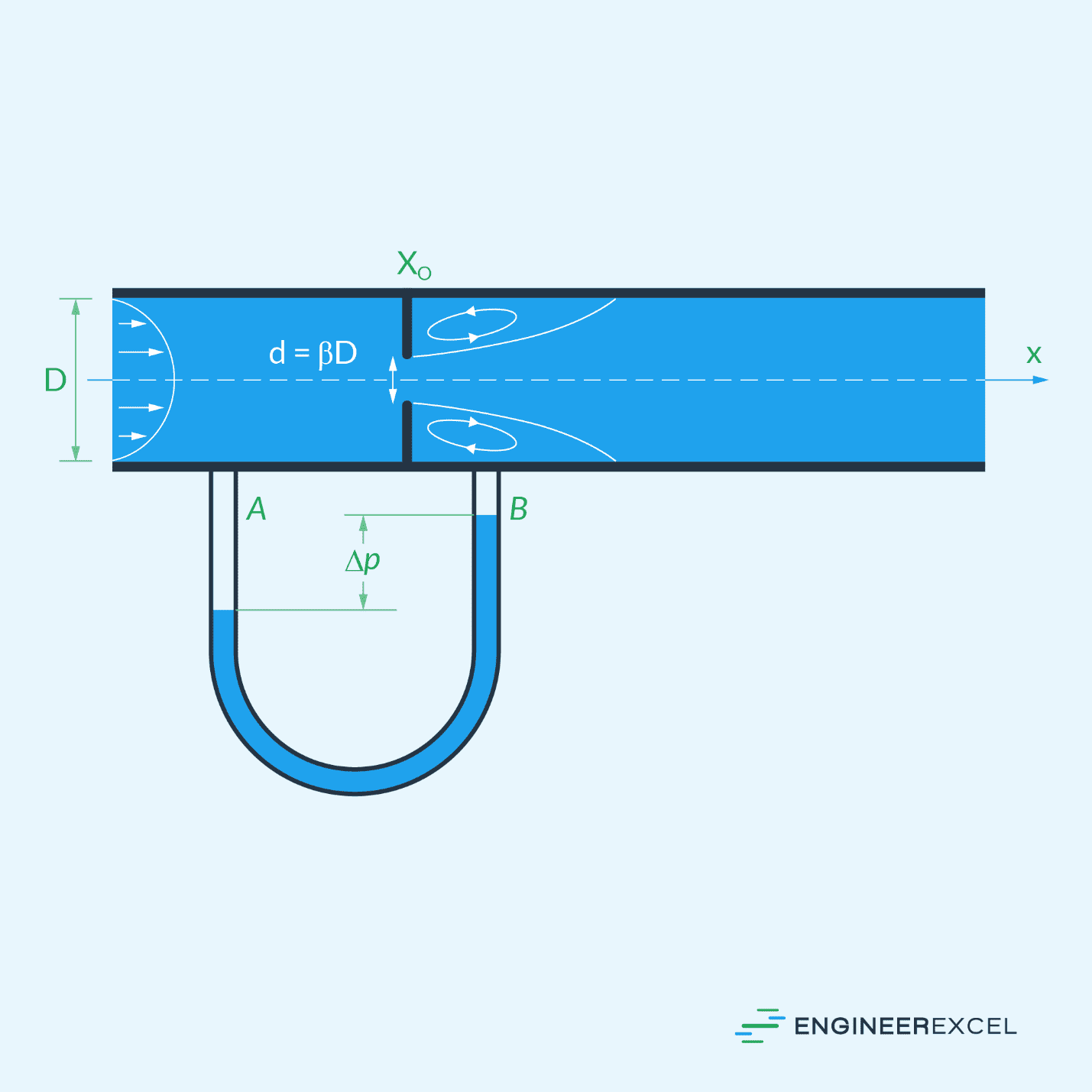
The orifice meter is a type of inferential flow meter that utilizes an orifice plate with an aperture that is concentrically inserted into a pipeline in order to create the required constriction in the flow path. It operates on the idea that a decrease in flow area causes an increase in velocity as well as a decrease in pressure. The typical flow pattern across an orifice plate is shown in the diagram below.

Elevate Your Engineering With Excel
Advance in Excel with engineering-focused training that equips you with the skills to streamline projects and accelerate your career.
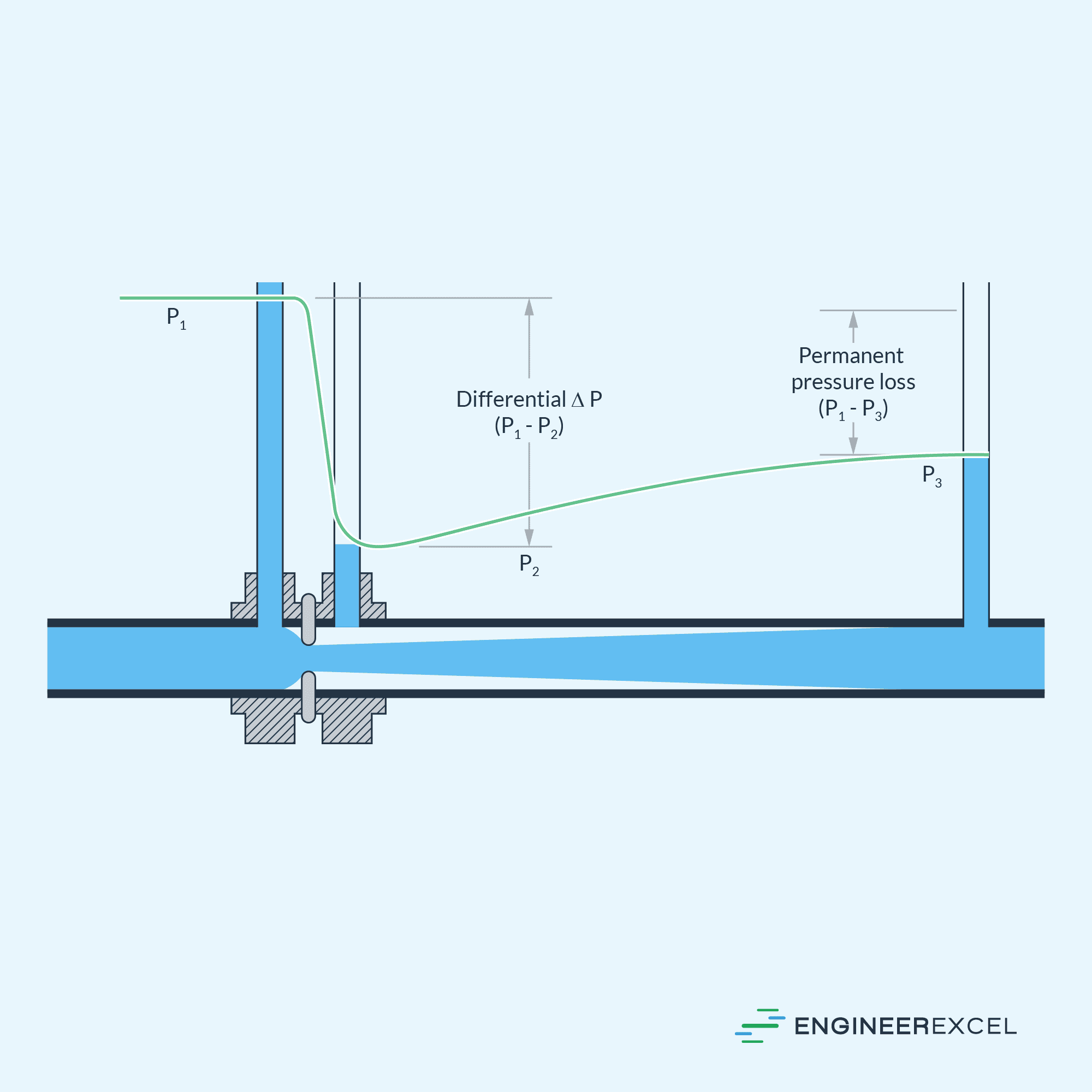
As the fluid approaches the orifice, the pressure slightly increases and reaches a maximum point followed by a sudden drop as it passes through the orifice. The pressure continues to decrease until it reaches the lowest point at the narrowest section of the flow called the vena contracta.
The pressure differential developed across the orifice is typically measured using a manometer and is used to empirically obtain the flow rate. As the pressure differential increases, the flow rate also increases. Generally, the pressure differential is proportional to the square of the flow velocity.
It is important to note that after passing through the vena contracta, the velocity of the fluid decreases and the pressure tends to increase back to its original value. However, due to friction and turbulence losses, a large fraction of the pressure drop is not recovered. At a distance of approximately 5 to 8 diameters downstream, a new maximum pressure point is reached, which is lower than the maximum pressure upstream of the orifice, as shown on the flow pattern diagram above.
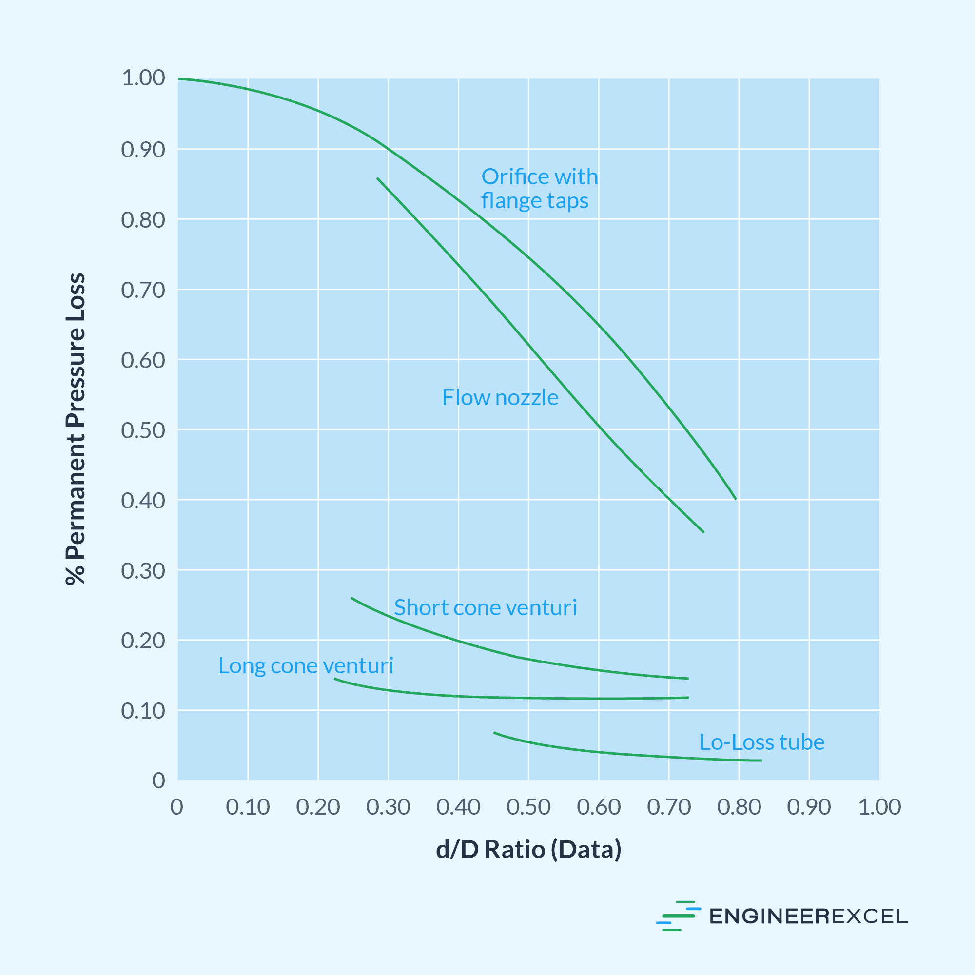
The permanent pressure loss is a function of a parameter called the beta ratio, as shown in the graph below. The beta ratio is the ratio of the diameter of the orifice plate bore to the internal diameter of the pipe.
Orifice Meter Flow Measurement
The measured pressure drop across the orifice can be used to obtain the flow rate using empirical equations. Derived from the Bernoulli’s equation, the actual volumetric flow rate through an orifice be calculated using the formula:
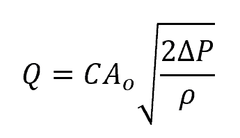
Where:
- Q = volumetric flow rate [m3/s]
- Ao = cross-sectional area of the orifice [m2]
- C = orifice plate flow coefficient [unitless]
- ΔP = pressure differential across the orifice [Pa]
- ρ = fluid density [kg/m3]
Note that this formula is only applicable for incompressible fluids. For compressible fluids, like gas, the equation needs to be modified to account for the effects of temperature, specific gravity, and gas expansion, among others.
The discharge flow coefficient is an empirical parameter that is introduced into the equation to account for the effect of viscosity and turbulence in the behavior of the flow. Research has shown that this coefficient depends on the Reynolds number and beta ratio.
To illustrate this relationship, consider the graph below, which depicts the discharge coefficient plotted against the Reynolds number for a standard concentric orifice plate at various beta ratio values.
Discharge coefficient of standard concentric orifice plate as a function of Reynolds number and beta ratio
The discharge flow coefficient is obtained from experimental data and can be found in reference books. However, it is important to note that different orifice plate bore configurations exist, and the coefficient value may vary among them. Typically, it ranges from 0.6 to 0.9 for most orifices.
Applications, Advantages, and Limitations of Orifice Meters
The orifice meter is arguably the most commonly used differential flowmeter in a wide range of industries such as oil and gas, water treatment, chemical processing, HVAC systems, and power generation. Since it essentially only consists of an orifice plate and pressure taps, it is simple and cost-effective compared to other types of flow meters.
Because of its long history of usage, orifice meters have established standardized measurement techniques. When properly applied, designed, installed, maintained, and interpreted, it provides highly accurate measurements.
However, orifice plates have some limitations. Firstly, they have limited turndown, meaning they may not provide accurate measurements at extremely low or high flow rates. Turndown is the ratio of maximum flow to minimum flow throughout which the accuracy of measurement is maintained. The turndown ratio of orifice meters is generally between 3:1 and 5:1.
Another limitation is the substantial permanent pressure loss caused by the obstruction created by the orifice plate. This makes orifice meters unsuitable for low-pressure systems as the additional pressure drop can significantly impact the overall system performance. When used with highly viscous fluids or slurries, the pressure drop can also become excessively high, resulting in inaccurate flow measurements.
Orifice meters are also not suitable in systems with non-homogeneous flow patterns, such as flows with presence of gas bubbles or solid particles. In general, orifice meters are designed for measuring the flow of clean, low-viscosity fluids. However, there are orifice plate configurations, such as the eccentric bore type, that can handle minimal amounts of impurities.
Lastly, orifice meters operate optimally under steady-state flow conditions with a well-developed flow profile. Fluctuations in flow rate, such as pulsating or oscillating flows, can affect the accuracy of the measurement due to the inertia and response time of the measurement system.
Despite these limitations, orifice meters are widely used due to their simplicity, cost-effectiveness, and acceptable level of accuracy for a range of flow rates. In the oil and gas industry and power generation, orifice meters are extensively used for measuring natural gas in pipelines, refineries, production facilities, and distribution networks.
In chemical processing and water treatment, they are used to measure flow rates of various liquids to control and optimize production processes. They are also employed in irrigation systems for measuring water flow in agricultural applications.
In HVAC systems, orifice meters can measure the flow of air and other gases to balance airflow in ductwork, monitor ventilation rates, and assess system performance.
Orifice Meter vs Venturi Meter
The orifice meter is a widely used flowmeter. However, it is important to note that there are also other inferential flowmeters that operate on the same principle of creating a constriction to indirectly measure flow rate from the pressure differential. One such device similar to the orifice meter is the Venturi meter.
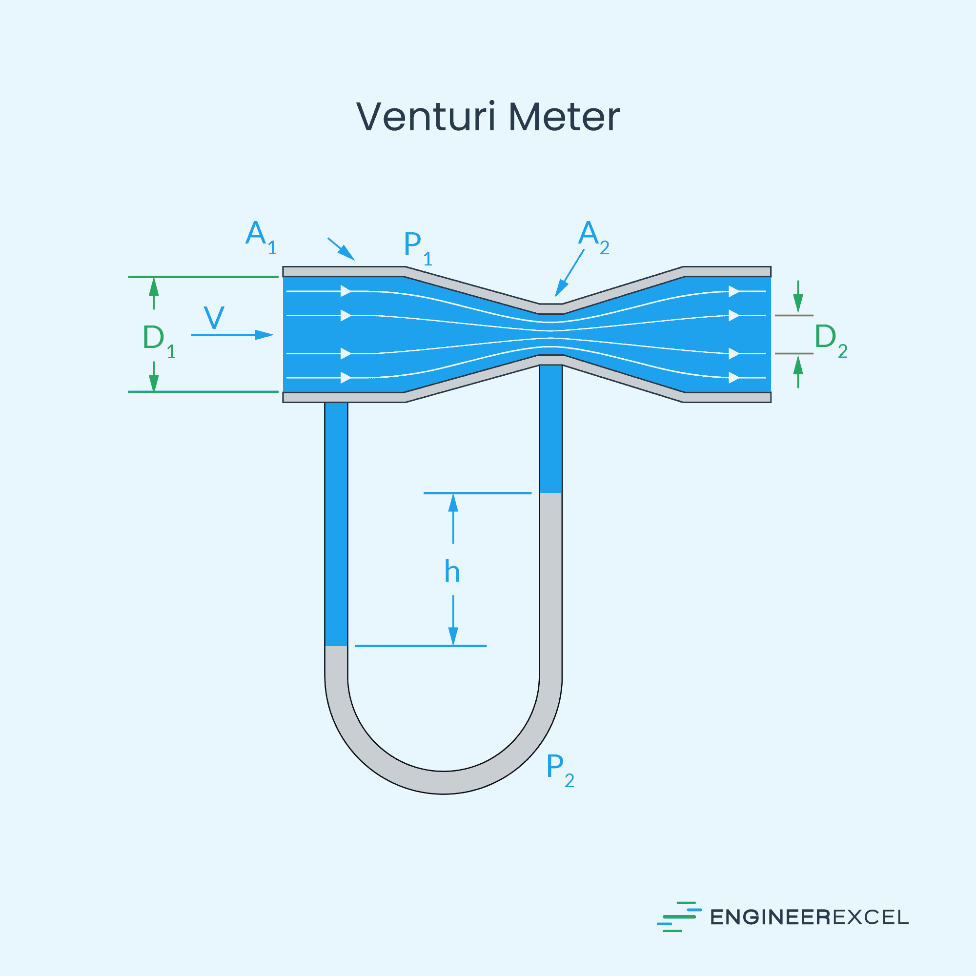
A Venturi meter consists of a converging section, a throat, and a diverging section.
As fluid enters the Venturi meter, its velocity gradually increases through the converging section, reaching its peak velocity at the throat. At the throat, the pressure is at its lowest point, but it increases again as the fluid exits through the diverging section and returns to the full pipe diameter. The pressure differential is measured between the inlet pipe and the throat.
Both the orifice and Venturi meters serve the same purpose. The main difference, however, lies in their structures. The Venturi meter has a tapered structure, causing a gradual change in fluid velocity, while the orifice has a sudden change in fluid velocity due to the flat plate.
Due to this structural difference, the Venturi meter offers several advantages in terms of functionality. It experiences much lower pressure loss compared to orifice meters and has a higher turndown ratio, which can reach up to 10:1.
The Venturi meter is also insensitive to changes in the velocity vector, allowing it to be installed in pipes oriented horizontally, vertically, or at any angle. On the other hand, the orifice meter must be installed on straight pipes, with the fluid’s velocity vector perpendicular to the orifice plate.
Additionally, Venturi meters can be used even with liquids containing a high solid content because the design of the Venturi meter allows for the flowing fluid to follow a streamlined path, which prevents clogging. In contrast, the orifice meter is generally not suitable for such working fluids as the flat plate creates dead zones where solids may deposit and accumulate over time.
Despite these advantages, Venturi meters are more expensive to install. Creating a tapered pipe requires ample space before and after the throttle area, and Venturi meters are permanently constructed into the pipe. On the other hand, the orifice meter is simpler and cheaper to install since it is simply inserted concentrically into the pipe.
Moreover, orifice meters offer more flexibility during operation. Although Venturi meters can handle a larger range of fluid flow rates than orifice meters, once a Venturi meter is already installed in a system, the range of flow rates it can handle becomes fixed. With orifice meters, the orifice plates can be easily removed and replaced with different plates containing varying bore sizes or arrangements.