
Orifice plates are thin plates containing holes intended for the purpose of creating a restriction along a pipeline. This restriction serves to regulate flow or determine flow rate based on the pressure differential generated across the orifice.
They are offered in various sizes to cater to specific applications, and this article explores the different sizes available, guidelines for sizing orifice plates, the factors influencing the selection of plate size, and the impact of plate size on fluid flow.
Orifice Plate Sizes
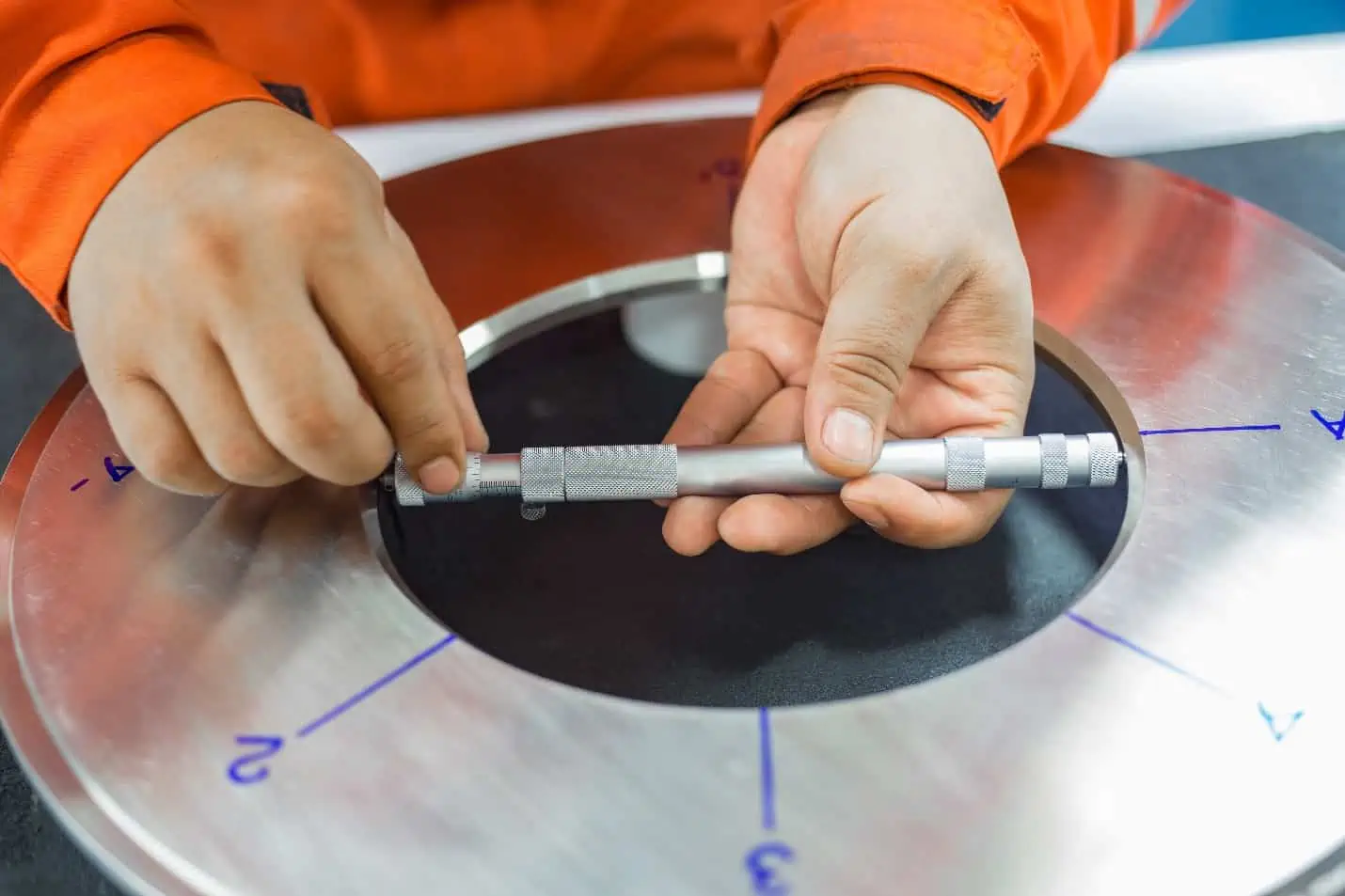
An orifice plate is a thin, flat plate in which a precisely sized hole has been machined with a sharp and square upstream edge. It is commonly used to regulate or measure pipe flow in a wide range of industries like oil and gas, chemical processing, water treatment, and HVAC systems.
Orifice plates can have different bore configurations depending on application and fluid characteristics: concentric, eccentric, segmental, and quadrant.

Elevate Your Engineering With Excel
Advance in Excel with engineering-focused training that equips you with the skills to streamline projects and accelerate your career.
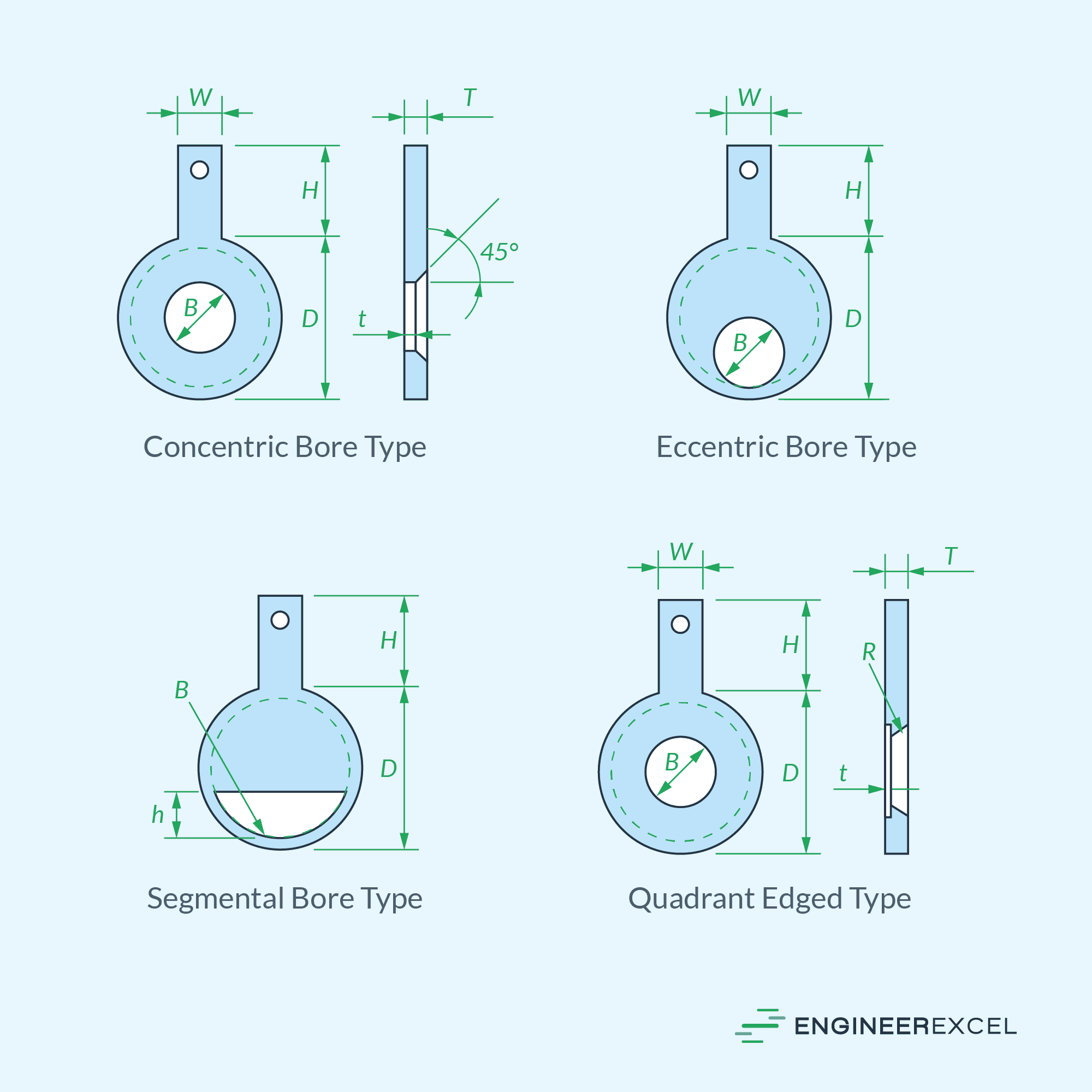
The most frequently used type is the sharp-edge concentric orifice plate which is used for clean gas or liquid systems. This type is preferred due to its lower cost, flexibility, and the availability of accurate coefficients.
The eccentric bore type is suitable for liquids that have gas or solid impurities present. When dealing with fluids that contain heavy sediment, the segmental bore type is the preferred choice. For fluids characterized by high viscosities or low Reynolds numbers, the quadrant edged type is the most suitable option.
This article is focused on concentric bore type orifice plates, as they are widely adopted as the standard for various general applications.
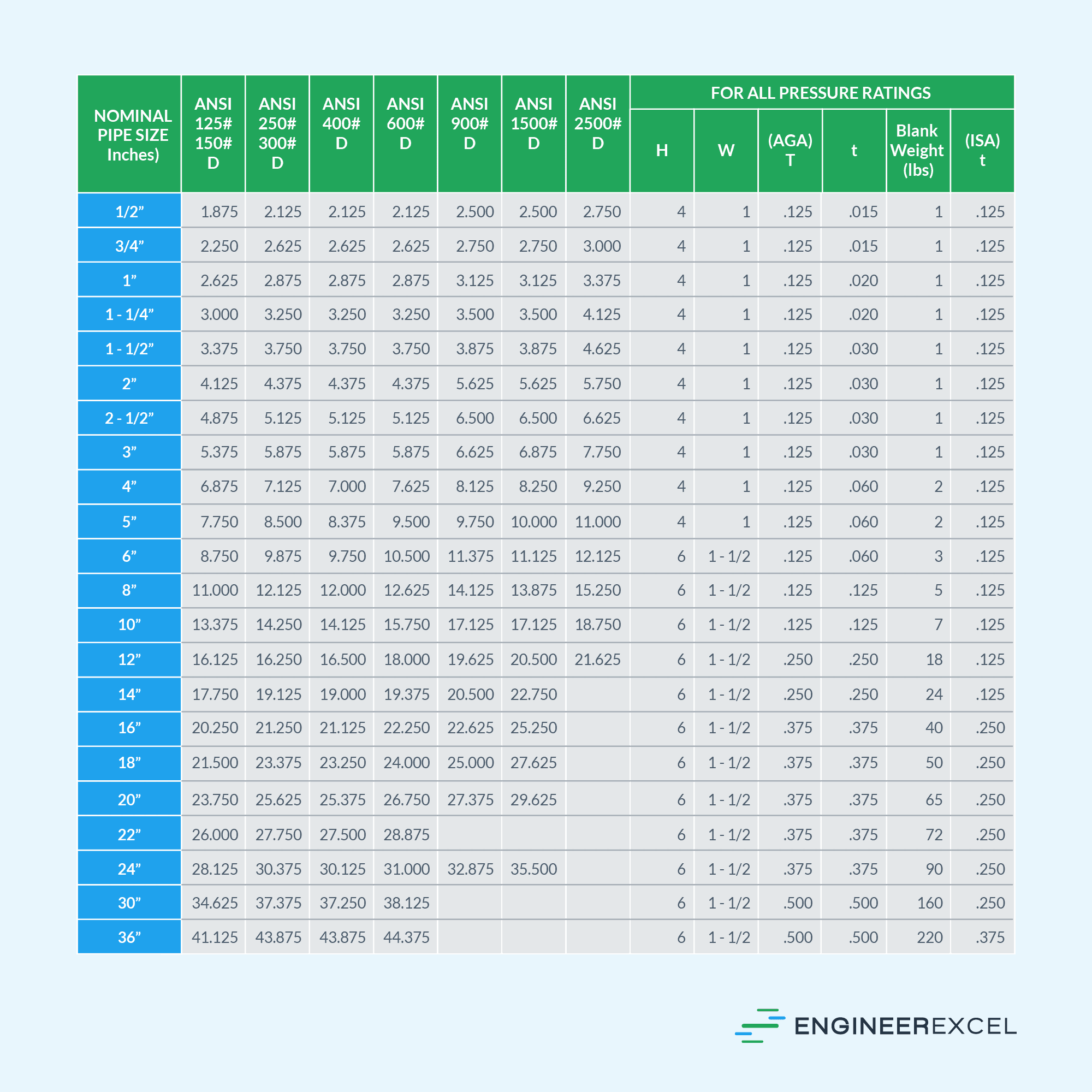
Apart from different hole configurations, orifice plates are also available in various sizes to accommodate different flow rates, pressure ratings, and pipe diameters. In general, they can be manufactured for line sizes ranging from ½ inch to 36 inches.
Manufacturers commonly include the following information when listing orifice plate sizes: plate diameter, handle dimensions including height and width, plate thickness, and bore size. These specifications vary across different pressure ratings and nominal pipe sizes, as illustrated in the table below.
Determining the appropriate dimensions for specific applications are based on industry-specific standards. For instance, the American Petroleum Institute (API) provides orifice plate size guidelines in API RP550 standards for petroleum, chemical, and gasoline installations.
Furthermore, the International Organization for Standardization (ISO) and the American Society of Mechanical Engineers (ASME) have developed general standards for measuring fluid flow using pressure differential devices, including orifice, nozzle, and Venturi, in circular cross-section conduits. These standards are outlined in ISO 5167 and ASME MFC-3M publications, respectively.
Orifice Plate Sizing And Design
When sizing and designing an orifice plate, there are various standards that can be followed. In this article, ISO 5167 is considered the primary reference, while API RP550 and ASME MFC-3M are treated as supporting references.
However, it is important to note that these standards are only guides. No publication of this type can be complete, nor can they substitute for qualified engineering analysis.
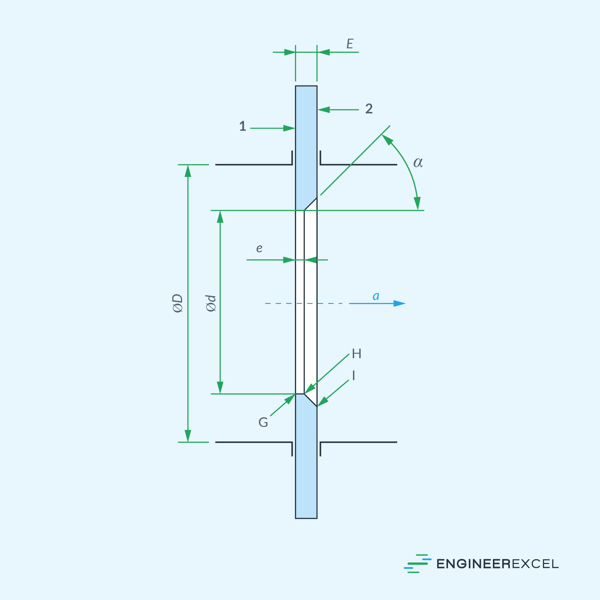
To ensure accurate sizing of orifice plates, several parameters need to be taken into account, including plate thickness, angle of bevel, plate diameter, and orifice diameter, among others. The following subsections will discuss the recommended values for these parameters, referring to the diagram of a standard concentric orifice plate provided below.
Orifice Thickness
ISO and ASME both prescribe that the thickness of the orifice or bore shall satisfy the following condition:
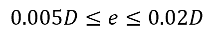
Where:
- e = thickness of the orifice [mm or in]
- D = inside diameter of the pipe [mm or in]
Plate Thickness
ISO and ASME both prescribe that the thickness of the orifice plate shall satisfy the following condition:
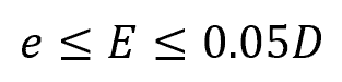
Where:
- E = thickness of the orifice plate [mm or in]
However, if the plate thickness is between 50 mm and 64 mm, a plate thickness of up to 3.2 mm is acceptable.
Angle Of Bevel
If the thickness of the plate exceeds that of the orifice, it should be beveled on the downstream side. This means that the sharp, square edge should face the upstream side, facing the incoming flow. The recommended bevel angle, α, is 45⁰ ± 15⁰.
Minimum Orifice Diameter
In all cases, ISO and ASME prescribe that the orifice or bore diameter must be equal to or greater than 12.5 mm. However, API sets a slightly higher minimum requirement for orifice diameter at 12.7 mm due to the risk of plugging caused by pipe scale and foreign material, except for clean fluids.
In addition to this minimum requirement, the orifice diameter must also satisfy the beta ratio requirement, which is explained below.
Beta Or Diameter Ratio
The beta ratio is the ratio of the orifice and internal pipe diameters, as shown in the equation:
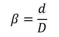
Where:
- β = beta ratio [unitless]
- d = diameter of the orifice [mm or in]
Based on ISO and ASME standards, the beta ratio should fall within the range of 0.10 to 0.75. However, API recommends a beta ratio of 0.20 or higher, but not exceeding 0.75 for liquids and 0.70 for gas or steam. Generally, a beta ratio between 0.4 and 0.6 is considered ideal.
Note that the diameter values are normally measured at working conditions. If measurements are conducted under varying conditions, it is necessary to make adjustments to consider any potential expansion or contraction of the orifice plate and pipe. These adjustments should take into account the fluid’s temperature and pressure during the measurement process.
Orifice Edge
The upstream orifice edge must have a sharp and square shape, with an edge radius less than 0.0004d and the angle between the orifice bore and the upstream face should be 90° ± 0.3°. On the other hand, the downstream edges have less stringent requirements as they are located within the separated flow region.
Impact Of Orifice Plate Size On Fluid Flow
When using an orifice plate to measure flow, the ideal scenario is that it does not impact the flow’s behavior. However, in reality, the size and configuration of the orifice plate do influence flow characteristics, including flow rate and pressure loss.
Flow Rate
The mass flow rate across an orifice can be calculated using the formula:
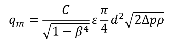
Where:
- qm = mass flow rate [kg/s]
- C = coefficient of discharge [unitless]
- Δp = pressure differential across the orifice [Pa]
- ρ = density of the fluid [kg/m3]
The flow rate is influenced by the diameter of the orifice and the beta ratio, as demonstrated in the formula above. When the diameter of the orifice and the beta ratio increase, assuming all other parameters remain constant, the flow rate also increases.
However, it is important to note that each orifice plate can only accurately measure a specific range of flow rates, known as the turndown ratio. The turndown ratio is the ratio between the maximum and minimum flow rates that an orifice plate can effectively measure.

The turndown ratio is limited due to the relationship between pressure drop and flow rate across the orifice plate. As the flow rate decreases, the pressure drop across the orifice plate decreases, making it challenging to obtain accurate measurements of pressure differential at low flow rates. Similarly, at high flow rates, the pressure drop can become too large, which may damage the meter or cause excessive energy losses.
Therefore, it is crucial to consider the expected minimum and maximum flow rates of the system when sizing an orifice plate. The turndown ratio for orifice plates typically ranges from 3:1 to 5:1, although with advanced designs and careful calibration, it can sometimes be extended to 10:1.
Pressure Loss
As the fluid flows through the orifice, its static pressure initially decreases due to the increase in velocity. However, once it passes through the orifice, the velocity decreases again, causing the static pressure to rise towards its original value.
However, due to factors such as friction and turbulence losses, a significant portion of the static pressure is lost. Hence, the pressure downstream is typically lower than the initial pressure.
The permanent pressure loss can be calculated using the formula:
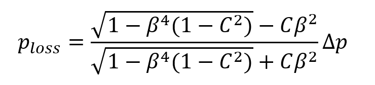
Where:
- ploss = pressure loss [Pa]
The pressure loss is influenced by the beta ratio, as shown in the equation above. When the beta ratio increases, the pressure loss decreases, and vice versa.