
It is important to know and control the velocity of water in a piping system as it directly influences the system performance and lifespan. Excessive velocities can induce damage to the piping material and result in higher pressure losses, while low velocities may lead to sedimentation and insufficient flow rates.

This article tackles water flow velocity in pipes, its calculation, and the recommended velocity limits to ensure optimal performance and longevity.
Water Velocity In Pipes
Velocity refers to how fast water moves through a pipe, typically measured in meters per second (m/s) or feet per second (ft/s). The speed of water flow has a significant impact on the entire piping system.
One crucial effect is its influence on pressure loss within the pipe. As water moves, friction between the water and the inner surface of the pipe creates resistance, leading to pressure loss in the direction of flow. Higher water velocities result in greater pressure loss, leading to increased energy consumption and reduced efficiency.

Elevate Your Engineering With Excel
Advance in Excel with engineering-focused training that equips you with the skills to streamline projects and accelerate your career.
Additionally, high water velocities can cause erosion within the pipe, which becomes particularly concerning in industrial settings where the water may contain abrasive particles. Over time, this erosion can lead to pipe degradation, leaks, and higher maintenance costs. Hence, understanding the behavior of water velocity in pipes is important in designing effective water piping systems.
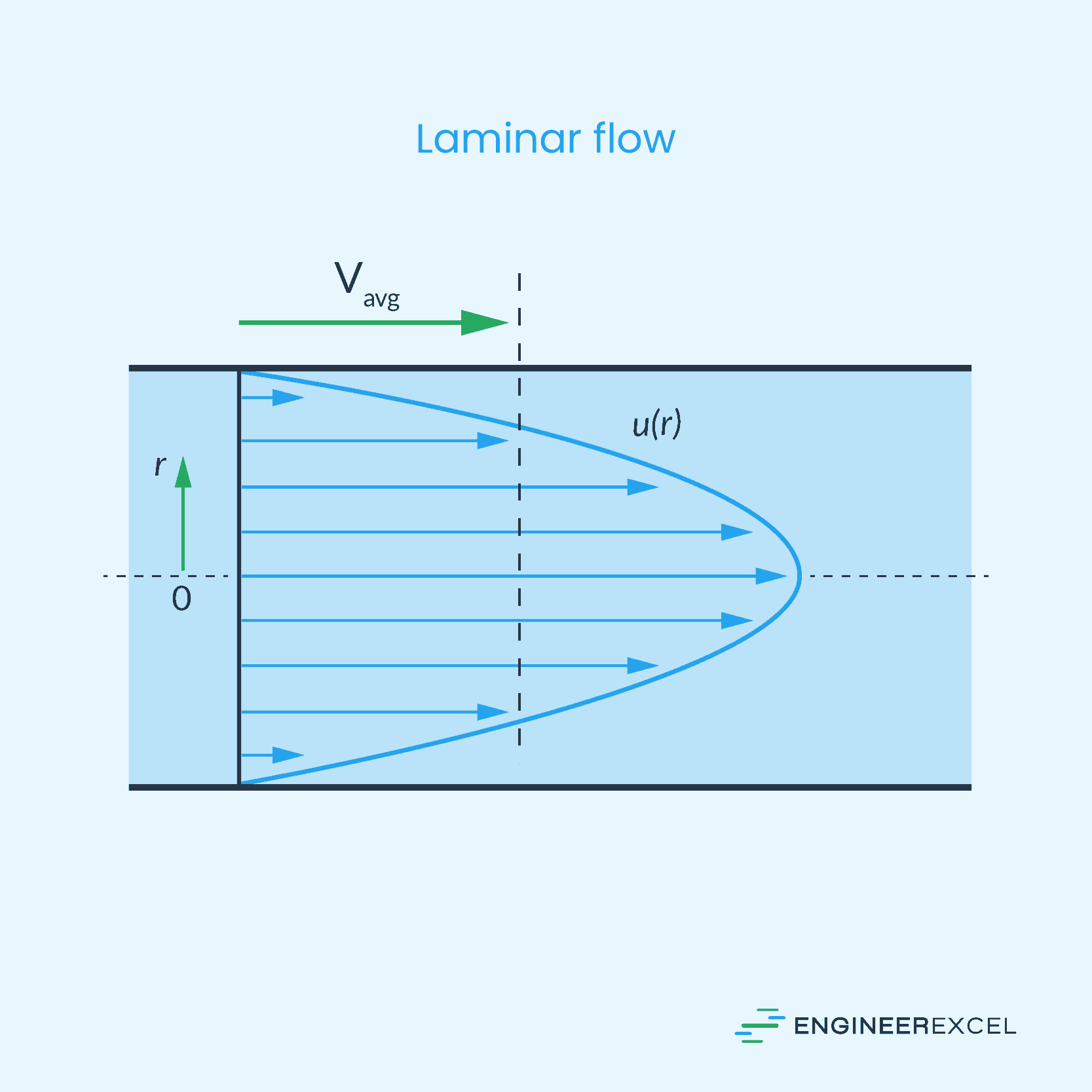
The velocity profile of water flowing through a pipe varies based on the flow regime. In fully developed laminar flow, the velocity profile is parabolic, with the highest velocity at the pipe center and zero velocity at the pipe wall due to no-slip condition. This is shown in the diagram below.
On the other hand, for turbulent flow, the velocity profile is flatter due to eddy motion and more vigorous mixing.
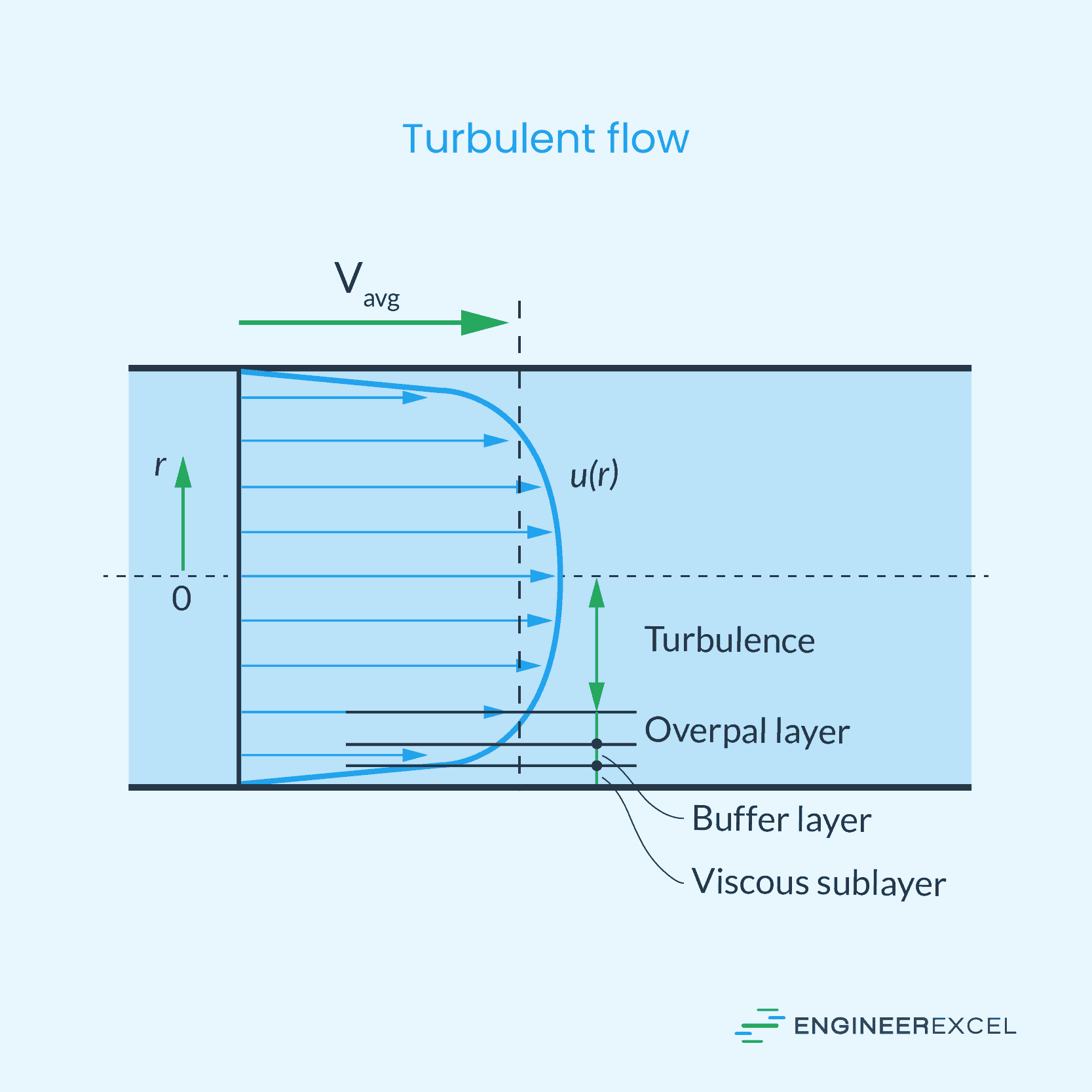
As shown in the velocity profile illustrations above, the velocity of water varies across the pipe’s cross-section. However, in fluid mechanics, it is often convenient to work with an average velocity, which remains constant in a fully developed flow.
In heating and cooling applications, this average velocity may experience slight changes due to variations in density caused by temperature fluctuations. However, for most practical purposes, these changes are usually negligible.
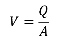
There are various methods to calculate the average velocity of water flowing through a pipe. The simplest equation is using the volumetric flow rate and the cross-sectional area of the pipe as follows:
Where:
- V = mean water velocity [m/s]
- Q = volumetric flow rate [m3/s]
- A = cross-sectional area of the pipe [m2]
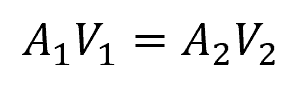
Based on the principle of conservation of mass, the mass flow rate of water remains constant along a pipe. For an incompressible fluid like water, the water flow velocity can be calculated using the continuity equation in the following form:
Where:
- A1, A2 = cross-sectional area of the pipe at two different locations [m2]
- V1, V2 = mean water velocity at two different locations [m/s]
Finding Water Velocity in Pipe Under Pressure
For pipes under pressure, the velocity of water can be calculated from the pressure difference across two points using the rearranged Darcy-Weisbach equation as follows:
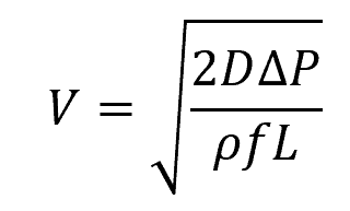
Where:
- ΔPL = pressure drop across two points along the pipeline [Pa]
- f = Darcy-Weisbach friction factor [unitless]
- L = length of pipe [m]
- D = hydraulic diameter of the pipe [m]
The Darcy-Weisbach friction factor is a dimensionless parameter whose value depends on the Reynolds number and roughness of the pipe surface. It is typically estimated using the Moody chart.
For laminar flow, water velocity can also be calculated using the following formula:
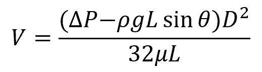
Where:
- θ = angle of inclination of the pipe with respect to the horizontal [rad or deg]
- μ = viscosity of water [10-3 Pa-s]
- g = gravitational acceleration [9.81 m/s2]
Finding Water Velocity In Pipe Under Gravity
For pipes under gravity flow, the water velocity can be calculated using the Manning formula:

Where:
- Rh = hydraulic radius [m]
- S = slope of the pipe [unitless]
- n = Manning’s roughness coefficient [unitless]
The Manning’s roughness coefficient is a dimensionless parameter that represents the effect of the relative roughness of the surface of the pipe to fluid flow, which can range from 0.01 for smooth surfaces to 0.03 for very rough surfaces.
Water Velocity Limits In Pipes
The optimal water velocity for a piping system depends on its intended use. However, some general guidelines exist to help maintain appropriate water velocities.
Recommended Minimum Water Velocity In Pipes
In wastewater systems, it is important to maintain a minimum flow velocity of around 0.7 m/s or approximately 2 ft/s to prevent sedimentation. When water flows too slowly, it lacks the energy needed to carry sediment and other particles effectively. These particles can settle at the bottom of the pipe, reducing its effective cross-sectional area and potentially causing blockage.
Additionally, low velocities can lead to stagnant water, promoting the growth of microbiological organisms like bacteria and algae. These organisms can multiply rapidly in slow-moving water, forming biofilms on the interior surfaces of the pipe. Biofilms not only affect water quality but can also lead to clogging and reduced water flow.
Ultimately, the minimum water velocity depends on the specific demand requirements of the system. For instance, in a building water distribution system, the demand is determined based on the number of water supply fixture units. As the demand flow rate increases, a higher water velocity or bigger pipe size is needed.
Recommended Maximum Water Velocity In Pipes
The maximum water velocity is typically limited to control pressure losses in the system. According to the Darcy-Weisbach equation, pressure losses increase with the square of the water velocity. Higher pressure losses make the system less efficient.
For water distribution piping within buildings, the National Standard Plumbing Code recommends sizing pipelines for a maximum velocity of 8 feet per second at the design flow rate unless the pipe manufacturer suggests a lower maximum velocity.
Another limiting factor for the maximum water velocity is the potential damage it can cause to the pipes and other components. Some designers use a somewhat arbitrary velocity threshold of 5 ft/sec, as beyond that, the danger of water hammer and pipe movement due to water momentum changes can become too high.
Water hammer, also known as hydraulic shock, is a phenomenon that occurs in plumbing systems when there is a sudden change in water flow velocity. It happens when a fast-moving water is forced to suddenly stop or change direction, causing a rapid increase in pressure within the pipe. In some applications, water hammer arrestors are used to absorb the shock, as shown in the diagram below.
