
Understanding the flow of energy is crucial in the analysis and design of piping systems. One effective approach to doing this involves establishing an energy equation that accounts for all energy losses and gains within the system.
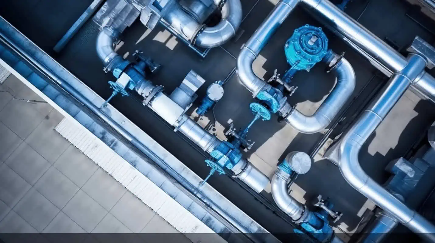
This article delves into the concept of the energy equation within the context of pipe flow systems.
Understanding Energy Equation and its Components
The Energy Equation is a fundamental equation in fluid mechanics that describes the relationship between the different types of energy present in a system. It is basically a mathematical formulation of the law of conservation of energy, which states that the rate of energy input into a system matches the rate of work done by the system on its surroundings plus the rate of energy accumulated within the system.
In general, the energy equation can be divided into several components, such as enthalpy, kinetic energy, potential energy, and other forms of energy, such as chemical reactions, nuclear reactions, electrostatic energy, and magnetic field effects, depending on what is present in the system. Furthermore, factors such as heat transfer, work done, and energy losses due to friction and momentum transfer must also be taken into account.

Elevate Your Engineering With Excel
Advance in Excel with engineering-focused training that equips you with the skills to streamline projects and accelerate your career.
Enthalpy
Enthalpy in fluid flow is a thermodynamic property that combines the internal energy with the pressure-volume work done by the fluid. Mathematically, enthalpy is defined as:
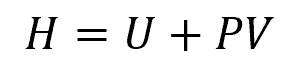
Where:
- H = enthalpy of the fluid [J]
- U = internal energy of the fluid [J]
- P = pressure of the fluid [Pa]
- V = volume of the fluid [m3]
Kinetic Energy
Kinetic energy is a form of mechanical energy associated with the motion of the fluid within the pipe. Its value is directly proportional to the mass and the square of the velocity of the fluid, as shown in the formula below:
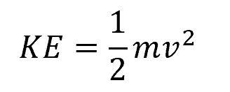
Where:
- KE = kinetic energy of the fluid [J]
- m = mass of the fluid [kg]
- v = fluid velocity [m/s]
Potential Energy
In the context of pipe flow, potential energy refers to the gravitational potential energy of the fluid. It is important to consider this, particularly when the fluid is flowing vertically or in piping networks involving changes in elevation. This energy is measured with respect to a reference point, which is typically a horizontal reference plane.
The formula for calculating the gravitational potential energy of a fluid in a pipe is:
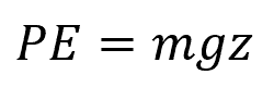
Where:
- PE = potential energy of the fluid [J]
- g = acceleration due to gravity [9.81 m/s²]
- z = height of the fluid above the reference plane [m]
Heat Transfer
Heat transfer in pipe flow happens when there is a difference in temperature between the fluid and the pipe wall. This occurs in many engineering applications, particularly in heating and cooling systems. Heat transfer in pipe flow can occur either through conduction, convection, or radiation.
Work Done
In addition to heat transfer, it is crucial to consider the work done on or by the fluid in the energy equation. This work can occur in various ways and can be either positive or negative, depending on the energy flow’s direction.
For instance, in a hydroelectric power plant, the fluid’s force as it flows over the turbine blades causes the turbine to rotate, converting the fluid’s energy into mechanical work done by the turbine. Conversely, in a pump, a rotating impeller is used to increase the fluid’s pressure or flow rate, and the impeller expends mechanical work to transfer energy to the fluid.
Major Losses
Major losses refer to energy losses caused by friction in pipe flow. These losses occur as a result of the resistance the fluid encounters as it flows along the inner surface of the pipe.
Friction losses are influenced by several factors, such as the roughness, diameter, and size of the pipe, as well as the fluid velocity and flow regime. These can be calculated using various equations, such as the Darcy-Weisbach equation or the Hazen-Williams equation.
Minor Losses
In contrast, minor losses, also known as local losses, refer to the energy losses that occur within a pipeline due to various factors other than friction. These losses are typically associated with abrupt changes in flow direction, variations in pipe diameter, and the presence of certain fittings or components in the pipeline.
Energy Equation in Pipe Flow Systems
In pipe flow systems, the form of the energy equation depends on the flow conditions. In this article, two forms commonly encountered in pipe flow analysis are discussed: Bernoulli’s Equation and the general form of the energy equation.
Bernoulli’s Energy Equation in Pipe Flow
The Bernoulli equation is a simplified form of the energy equation that assumes the following conditions:
- Steady flow: The flow is not changing with time.
- Incompressible fluid: The density remains constant.
- Inviscid flow: Viscous effects are neglected such that there are energy losses due to friction.
- Along a streamline: The equation applies along a single path or streamline.
- No heat transfer: It assumes there is no heat exchange with the surroundings.
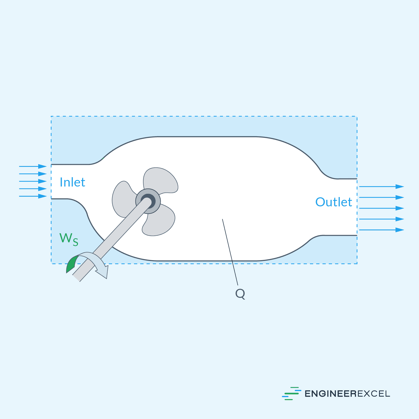
For numerous engineering applications, these assumptions are adequate; therefore, Bernoulli’s equation is frequently employed. To illustrate, consider the diagram of a converging section of pipe shown below.
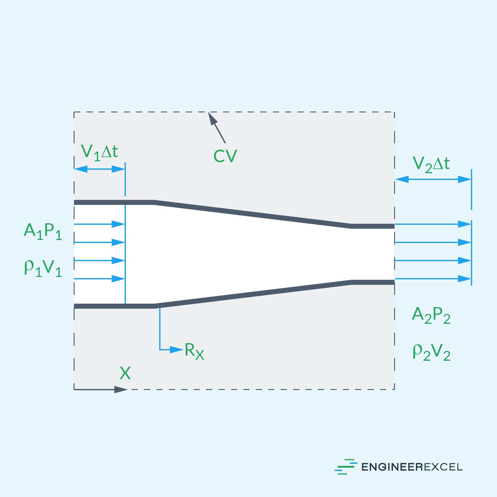
Bernoulli’s equation states that the sum of energy per unit volume in the form of pressure, kinetic, and potential energy remains constant along a streamline. Based on the diagram above, the simplified Bernoulli’s equation for pipe flow can be mathematically expressed as:
Where:
- ρ = density of the fluid [kg/m3]
General Energy Equation in Pipe Flow
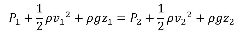
While Bernoulli’s equation is sufficient for many engineering applications, the more comprehensive form of the energy equation takes into account additional factors, including heat transfer, work done, and energy losses, among others. To illustrate, consider the diagram below:
Based on the diagram above, the general energy equation can be written in terms of heads as follows:
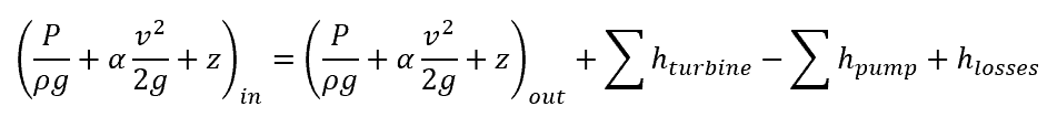
Where:
- α = kinetic energy flux correction factor [unitless]
- hturbine = head loss due to work done on the turbine [m]
- hpump = head added due to work done by the pump [m]
- hloss = sum of major and minor losses in the system [m]
Note the addition of the flux correction factor on the kinetic energy term. The kinetic energy flux correction factor accounts for the variation in kinetic energy flux across the cross-sectional area of the pipe. This is due to the fact that the velocity profile across the cross-section is typically not uniform, with a peak velocity at the center of the pipe, decreasing towards the pipe wall.
Applications of Energy Equation in Pipe Flow Systems
The energy equation is a crucial tool for engineers designing and analyzing pipe flow systems, ranging from HVAC and water distribution systems to oil and gas pipelines. In general, it helps determine operational parameters such as flow rate, fluid velocity, and pressure losses, enabling accurate system design. Engineers use the energy equation to design efficient piping systems by considering energy losses due to friction and elevation changes, allowing for appropriate pipe diameters and pump sizes to be selected.

Additionally, the energy equation is central to pump and turbine sizing. It is used to calculate the required pump or turbine head needed to achieve the desired flow rate, ensuring optimal system performance.
Lastly, the energy equation aids in calculating pressure drop within pipelines due to friction and elevation changes, which is crucial for assessing system efficiency and ensuring pressure remains within acceptable limits.