
In fluid dynamics, the terms upstream and downstream are used to describe the direction of fluid flow within a pipe network. The meaning of upstream and downstream can change depending on the situation, but in most cases, upstream indicates the direction in which fluid enters the system, while downstream indicates the direction in which fluid exits the system.
This article explores the differences between these two fundamental concepts.
Upstream Pipe Flow Explained
In general, upstream flow refers to the flow of a fluid, such as water or gas, in a direction opposite to the direction of the main flow or current. For example, in a river, upstream flow refers to the movement of water against the current, towards the source of the river.
In the context of pipe networks, the direction of flow is determined by the pressure gradient which moves fluid from areas of high pressure to areas of low pressure. The upstream flow, in this case, refers to the fluid moving towards the point of origin or source of the fluid, such as a reservoir or a pump.

Elevate Your Engineering With Excel
Advance in Excel with engineering-focused training that equips you with the skills to streamline projects and accelerate your career.
Upstream flow may be required during pipeline maintenance and inspection to allow safe access to specific sections of the pipeline. Cleaning of pipelines may also involve pushing cleaning pigs or other devices through the pipe against the normal flow direction to remove debris and buildup.
In certain industries like oil and gas, upstream flow is used for testing the integrity of pipelines, checking for leaks, and conducting pressure tests. In emergency situations, upstream flow may be necessary to prevent or mitigate potential hazards or redirect the flow of fluids away from dangerous situations.
It is crucial to understand the direction of upstream flow in designing and operating pipe networks as it can affect the efficiency and effectiveness of the network. A blockage or restriction in the upstream flow can cause a decrease in pressure and flow rate downstream, leading to operational problems and reduced performance.
Downstream Pipe Flow Explained
In contrast, downstream flow refers to the flow of a fluid in the direction of the main flow or current. For example, in a river, downstream flow refers to the movement of water in the direction of the current, towards the mouth of the river or its eventual discharge into the ocean.
In the context of pipe networks, downstream flow refers to the movement of fluid from the higher pressure or elevation end (the source) to the lower pressure or elevation end (the destination or outlet).
As fluid flows downstream, it may experience changes in flow rate, pressure, and energy. These changes can occur due to factors such as pipe diameter variations, the presence of obstacles or valves, and changes in the system’s configuration.
Upstream vs Downstream in Pipe Flow Measurement
When installing a flowmeter, it is essential to understand the concepts of upstream and downstream flow. Upstream refers to the direction of the fluid entering the flow meter, while downstream indicates the direction of the fluid exiting the flow meter. To obtain accurate flow measurements, long enough straight pipe sections are required before and after the flowmeter installation point, ensuring a uniform fluid flow state.
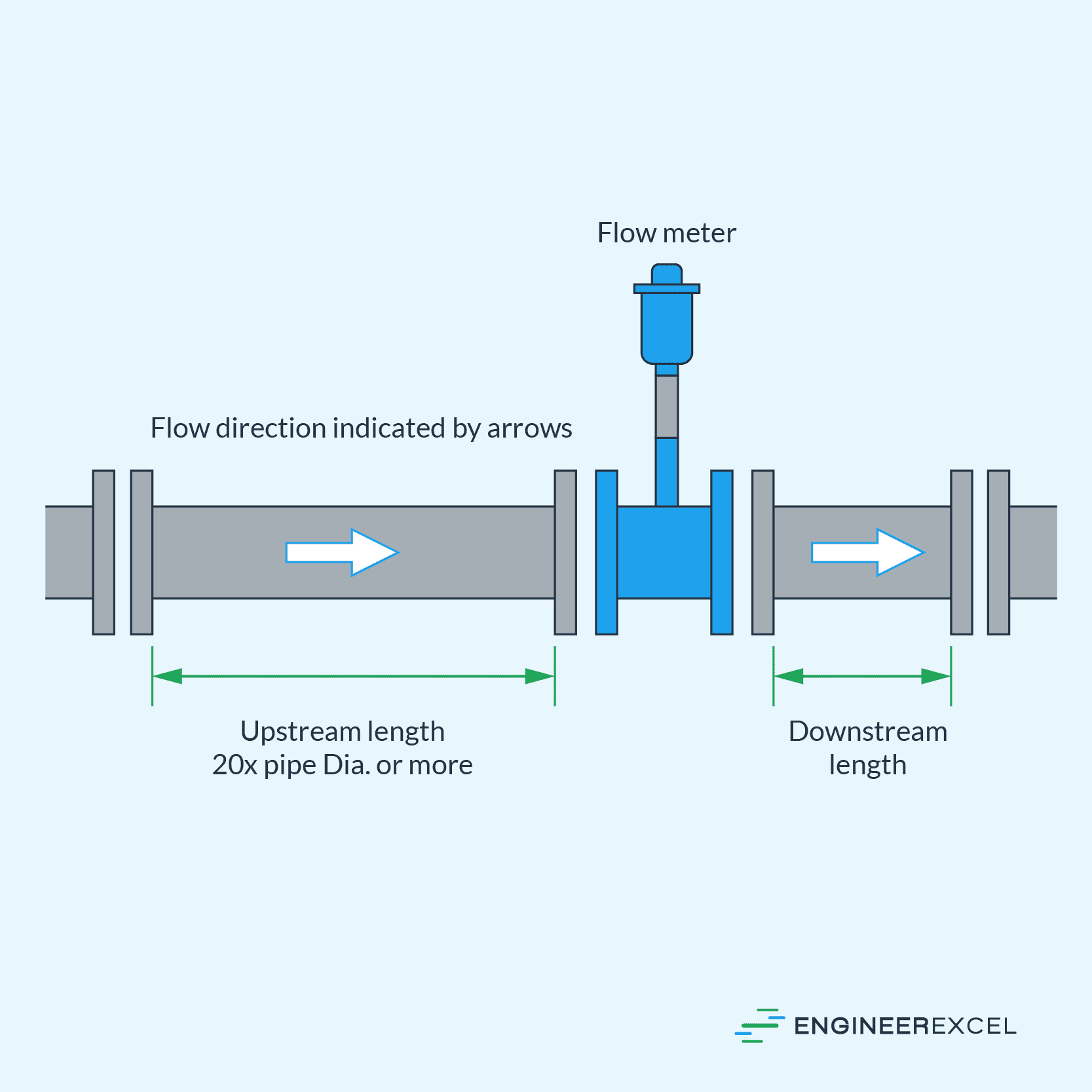
For general applications, a rule of thumb is to have a five-diameter length of piping upstream and a three-diameter length downstream from the center of the flow meter. However, this largely depends on the type of flowmeter.
For obstruction flowmeters, for example, the required length of straight pipe section ranges from 10 to 62 diameter-lengths. This is because the required length depends on the opening ratio of the diameter of the obstruction and the pipe diameter. In general, the larger the opening ratio, the longer the required straight pipe section.
Various professional organizations provide guidance and standards for flow measurement techniques, including ISA, ISO, API, AGA, ASME, and ANSI. When unsure about flowmeter placement, it is recommended to refer to these guides, as they have been tested and offer a good starting point for proper flowmeter performance.
Upstream and Downstream Pipe Flow in Hydraulic Systems
When designing hydraulic systems, it is important to consider downstream and upstream pipe flow. To analyze these systems, a single hydraulic model should encompass both the upstream and downstream systems into a single pipe network model. This allows for the consideration of complex interactions between the systems.
One simplified approach is to use a single hydraulic grade line (HGL) to represent the HGL at the connection point between the two systems. However, this approach can be inaccurate during peak demand times such as fires or emergencies. A more accurate method would be to conduct a hydrant flow test at the connection point, producing a table of hydrant flow versus residual pressure (and HGL).
When multiple connections exist between upstream and downstream systems, the interactions between connection points need to be considered. One way to do this is to use a single flow test with hydrants adjacent to all connections. Alternatively, separate flow tests for each pressure zone may work when supply comes from different zones. Another approach is to use simulated flow tests using calibrated hydraulic model simulations, which offer the advantage of testing various boundary conditions.