
A torsion spring is a flexible, elastic object that stores and releases mechanical energy through twisting. It is widely used in mechanical systems that require rotational motion control like garage doors, suspension systems, braking systems, and agricultural machinery, among others.
This comprehensive guide aims to provide a thorough understanding of torsion springs, including their formulas, mechanics, and applications.
Torsion Spring Formulas
A torsion spring is a type of spring specifically designed to exert torque or rotational force when twisted.
Unlike traditional springs that generate linear force, the primary function of a torsion spring is to store rotational mechanical energy as it is twisted, and upon release, it exerts a restoring torque, bringing the spring back to its original position. The amount of torque exerted is directly proportional to the angle of twist, acting in the opposite direction.

Elevate Your Engineering With Excel
Advance in Excel with engineering-focused training that equips you with the skills to streamline projects and accelerate your career.
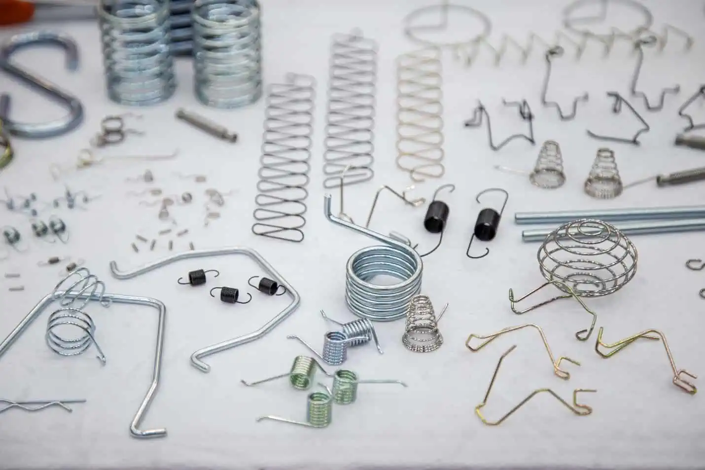
Torsion springs come in various types depending on application. Some take the form of spiral strips, rods, or bars. However, the most commonly used type of torsion spring is the helical torsion spring, which will be the primary focus of this article.
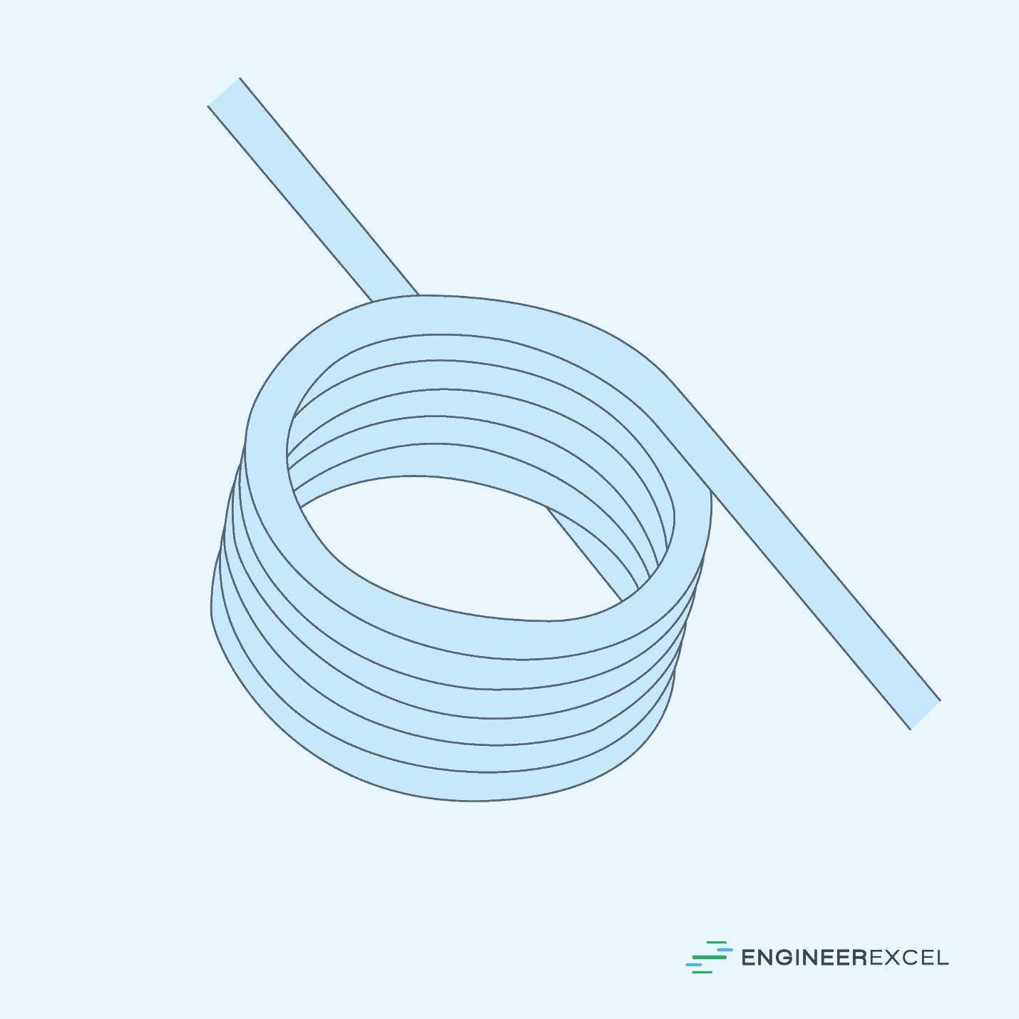
As shown in the photo above, a helical torsion spring is typically constructed by winding a wire in a coiled manner, configured such that its ends can be twisted around its axis. It can be fabricated from various materials, including high carbon steel, stainless steel, alloy steel, and non-ferrous metals such as bronze and copper.
Designing and analyzing the behavior of torsion springs require careful consideration of various parameters such as torque, spring constant, stress, load, energy, and spring geometry, among others. The following subsections discuss these parameters and their corresponding formulas.
Torque Of A Torsion Spring
The torque of a torsion spring refers to the rotational force exerted by the spring when it is twisted from its equilibrium position. This value is directly proportional to the angular displacement or twist applied to the spring and is given by the equation:
Where:
- T = torque of a torsion spring [N-mm]
- k = torsional spring constant [N-mm/rad]
- θ = angular deflection of the torsion spring [rad]
Note that this formula assumes a linear torsional spring with a constant stiffness. However, it is important to know that there are also nonlinear torsional springs that do not follow a linear relationship between the applied torque and angular deflection.
Two examples of such nonlinear torsional springs are the nonlinear stiffening spring and the nonlinear softening spring. In a nonlinear stiffening spring, the spring rate gradually increases as the spring deflection progresses. Conversely, in a nonlinear softening spring, the spring rate gradually decreases as the spring deflection increases.
Force Or Load On A Torsion Spring
When an external load is applied perpendicular to the leg of a torsion spring, it causes the spring to twist and generate torque. This is depicted in the diagram below.
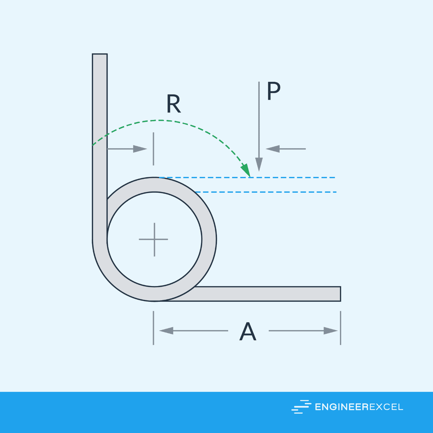
Assuming that the load is applied at the midpoint of the torsion spring’s leg, the load can be related to the torque using the formula:
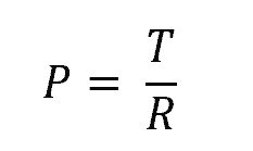
Where:
- P = direct load applied at the midpoint of the leg [N]
- R = distance between the midpoint and the center of the spring [m]
Torsional Spring Constant
The torsional spring constant, also known as the torsional spring rate or stiffness, indicates the spring’s resistance to twisting and determines the amount of torque needed to achieve a given angular deflection. It is analogous to the stiffness of traditional springs, denoted by the symbol k.
A higher torsional spring constant corresponds to a stiffer spring, requiring more torque to achieve a specific angle of rotation. Conversely, a lower torsional spring constant corresponds to a more flexible spring, requiring less torque.
The torsional spring constant is a physical property of the spring and is typically determined experimentally or calculated based on the spring’s geometry and material properties using the formula:
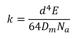
Where:
- E = longitudinal elastic modulus of the spring material [N/mm2]
- d = wire diameter [mm]
- Dm = mean coil diameter [mm]
- Na = number of active turns in the spring [unitless]
The formula above assumes a torsional spring constant with a unit of N-mm/rad. However, it is also possible to express the torsional spring constant in N-mm/turn. In this case, the formula becomes:
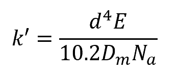
Where:
- k’ = torsional spring constant [N-mm/turn]
Note that these formulas ignore the presence of friction in between the coil. In reality, friction affects the apparent spring constant, especially in close-wound coils.
Angular Deflection
Unlike traditional springs, which deform linearly, torsional springs deform rotationally, and their deformation is measured in terms of angular deflection. Angular deflection refers to the angular distance that the leg of the spring has traveled from its free state to the loaded condition.
The total angular deflection is obtained by combining the twisting experienced in the body of the spring as well as the deflection at the end lengths. It can be calculated using the formula:
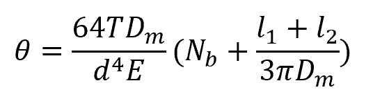
Where:
- θ = total angular deflection [rad]
- Nb = number of turns in the body of the spring [unitless]
- l1, l2 = ends lengths [mm]
The formula above assumes a deflection expressed in radians. However, it is also possible to express the deflection in terms of the number of turns. In this case, the formula becomes:
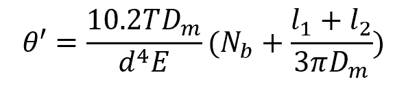
Where:
- θ’ = total angular deflection [turns]
The maximum deflection depends on the strength of the spring material used and the stress induced by the applied torque.
Stress On A Torsion Spring
When load is applied to a torsion spring, the wire experiences bending stress. While calculating the bending stress depends on the shape of the wire’s cross-section, in general, it can be obtained using the formula:
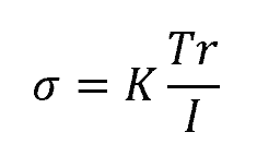
Where:
- σ = bending stress at the outermost fiber of the wire [Pa]
- K = bending stress correction factor [unitless]
- r = distance from the neutral axis to the outermost fiber [m]
- I = area moment of inertia of the wire’s cross-section [m4]
For a round wire torsion spring, this formula becomes:
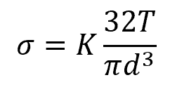
Where:
- d = diameter of the wire [m]
The bending stress correction factor, K, is a unitless parameter that is dependent on the spring index and aims to correct geometric deviations in the wire during deflection that causes the neutral axis to shift towards the center of curvature. This shift results in higher stress at the inner surface of the wire compared to the outer surface. Hence, the stress correction factor for the inner surface is always greater than the outer surface, as shown in the equations below.
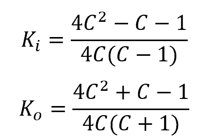
Where:
- Ki, Ko = stress correction factors for the inner and outer surfaces, respectively [unitless]
- C = spring index [unitless]
Remember that the spring index is simply the ratio of the mean coil diameter to wire diameter.
Diameter Reduction
When a torsion spring is under load and the direction of the load causes the spring to tighten, the mean diameter decreases with deflection according to the following relationship:
Where:
- Dm’ = new mean coil diameter at loaded condition [mm]
Torsion springs are typically used with a mandrel. When placing a spring over a mandrel, it is important to avoid contact between the inside of the coil and the mandrel even at fully loaded condition. A well-designed setup includes a diametral clearance between the spring and the mandrel that allows the spring to rotate smoothly without any interference from the mandrel.
Types Of Torsion Springs
Torsion springs come in different types and configurations, depending on their application.
For instance, the ends of the spring legs can be configured with a short hook, hinge ends, straight ends, or special ends to match the orientation of the applied load, as shown in the diagram below. Additionally, a double torsion spring can be designed with two coils wound in opposite directions, enabling the application of torque or rotational force in opposing directions.
Free Position Of Legs
In addition to varying end configurations, torsion springs can feature different leg angles at the free position. The most commonly used angles for torsion spring legs include 90°, 120°, 180°, 210°, 270°, 300°, and 360°, as depicted in the diagram below.
Direction Of Wind
The direction of wind determines how the coils of a spring are wound or spiraled. Springs can be wound in either a clockwise direction (right-hand wind) or a counterclockwise direction (left-hand wind). A good design practice is to use torsion springs in the direction that aligns with the coil winding.