
Manufactured machine components often vary from their designed dimensions due to inherent inaccuracies in the manufacturing process caused by various factors such as tool wear, machine vibrations, material properties, and other environmental conditions.

However, it is important to limit this variation in order to ensure functionality and interchangeability among mass-produced parts. In drilled components, this limit is defined by the drill tolerance.
Drill Tolerance
Drill tolerance defines the permissible limits or the acceptable range of hole size variation, while still meeting the necessary functional fit for the drilled component. To better understand drill tolerance, it is important to learn about the basics of drilling and how a drill machine operates.
A drill is a power tool primarily used for creating holes in materials like wood, metal, plastic, or masonry. It operates by rotating a cutting tool called a drill bit, which digs into the material to make a hole of a specific size and depth.

Elevate Your Engineering With Excel
Advance in Excel with engineering-focused training that equips you with the skills to streamline projects and accelerate your career.
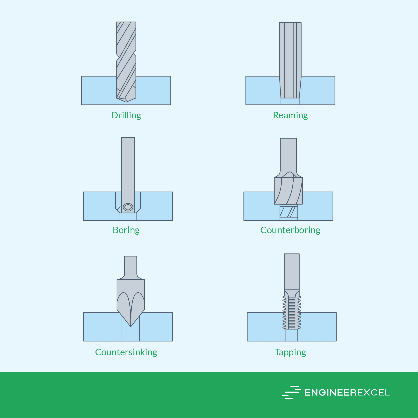
However, drills are versatile and can do more than just drilling. They are also used for operations like reaming, boring, counterboring, countersinking, and tapping, as shown in the diagram below.
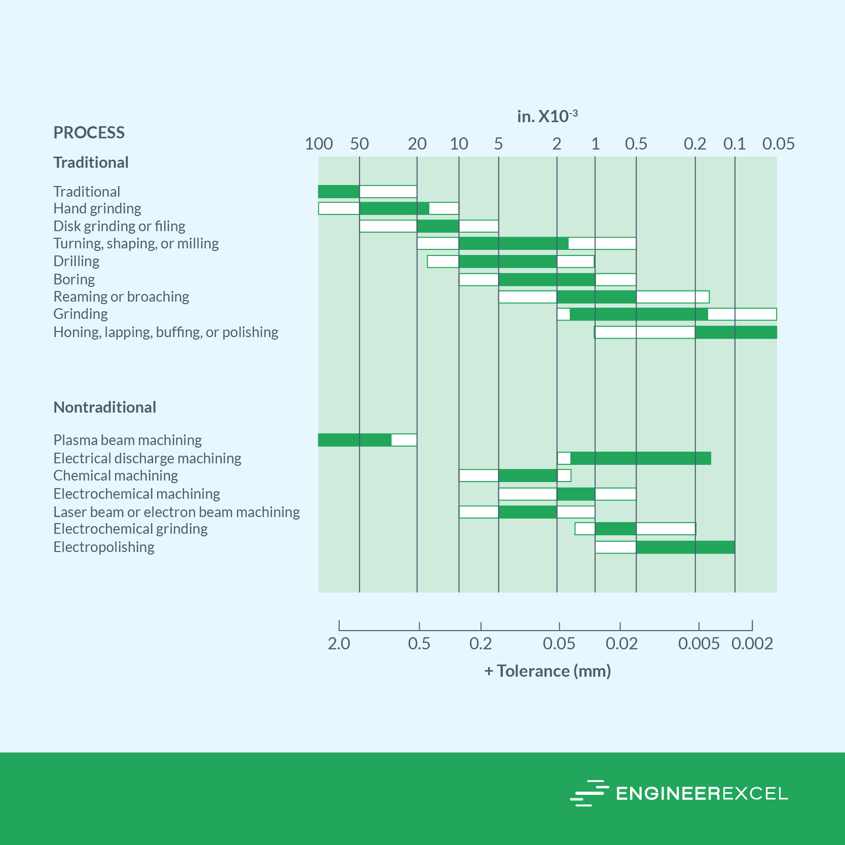
When working with drills, achieving precise hole dimensions is nearly impossible. In general, oversizing inherently occurs during the drilling process. This means that drilled holes are always slightly larger than the diameter of the drill’s original designation.
As shown in the diagram below, the tolerance for the drilling process typically falls between ±2×10⁻³ and ±10×10-3 inches.
This is where the concept of tolerance comes in. Tolerance is a measure of how much a dimension is allowed to vary.
In the context of drilling, tolerance refers to the acceptable variation in location and size of a hole within a component. This is important to consider especially that holes often serve as interfaces for fasteners, alignment pins, or fluid flow in intricate assemblies.
Ensuring the right hole tolerance requires careful consideration of the design parameters, properties of the material, and limitations of the drilling method. For example, different materials behave uniquely during drilling – brittle ones like ceramics need stricter tolerances to prevent cracking, while more flexible metals can have slightly looser tolerances.
The drilling method applied, whether twist drilling, gun drilling, or laser drilling, also affects tolerance. These methods introduce different levels of heat, vibrations, and tool wear that impact the final hole dimensions.
The precision of the drilling equipment matters, too. For example, modern CNC machines provide higher accuracy compared to conventional drilling machines, enabling tighter drill tolerances.
However, although tight tolerances are often preferable, it is important to consider that this often mean higher costs. Achieving high dimensional accuracy might require special tools, slower speeds, and careful process control, all contributing to higher production expenses. During the planning and design phase, it is essential to carefully evaluate these trade-offs.
Standards For Drill Tolerance
The specific standards used for drill tolerance can vary depending on the industry, application, and country. The internationally accepted standard is ISO 286 developed by the International Organization for Standardization (ISO).
Defining Drill Tolerance Using ISO 286
In the ISO 286 standard, the tolerance of a hole is defined by the tolerance class. Tolerance classes are alphanumeric symbols that contain two identifiers: the standard tolerance grade and the fundamental deviation.

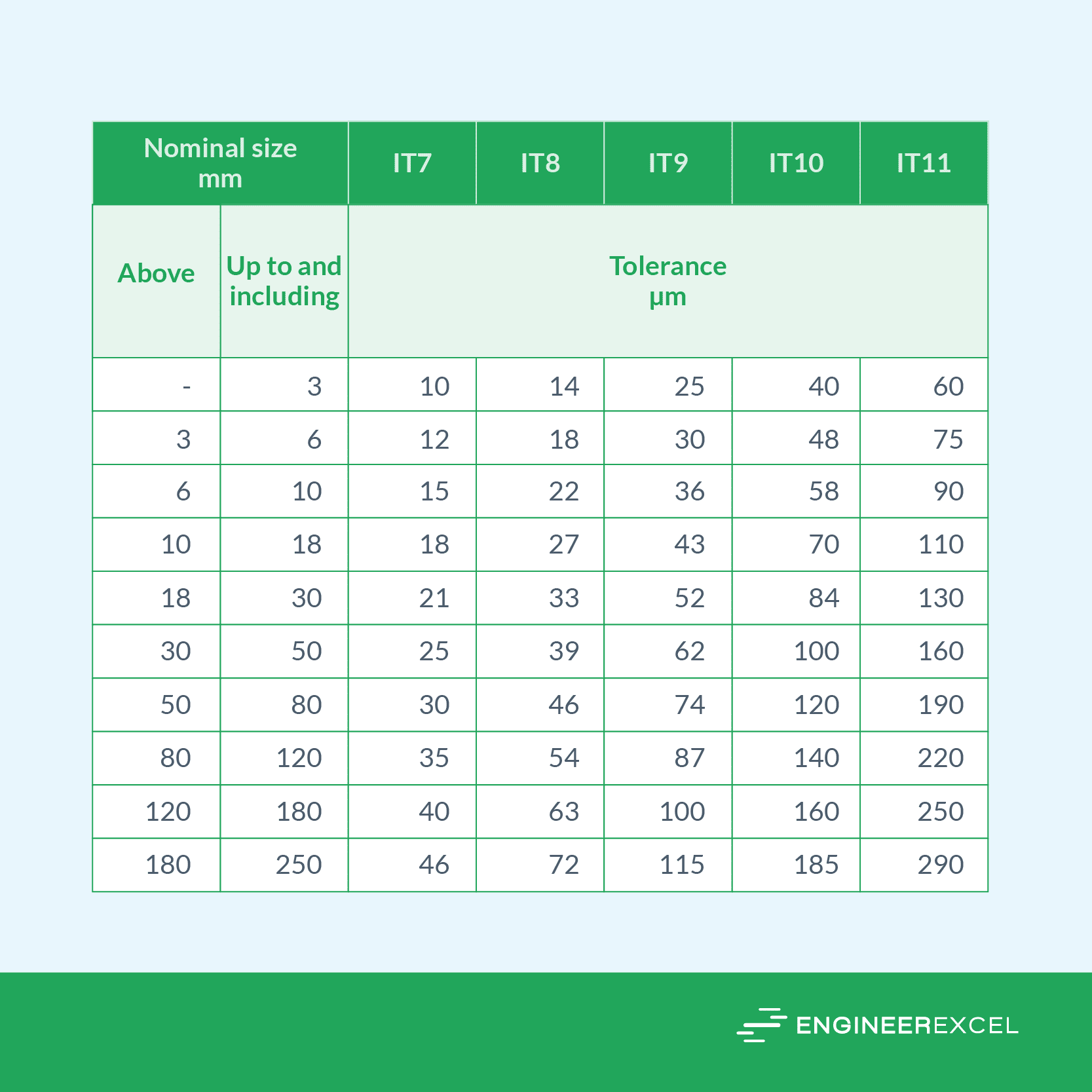
The standard tolerance grade indicates the magnitude of the tolerance interval with respect to the nominal size. A specific tolerance grade is considered as corresponding to the same level of accuracy across all nominal sizes. It is designated by the letters “IT,” which stands for International Tolerance, followed by the grade number, e.g., IT6.
The values of the standard tolerance grades for nominal sizes up to 250 mm are shown in the table below.
ISO 286 Standard Tolerance Grades
On the other hand, the fundamental deviation indicates the tolerance interval’s position relative to the hole’s nominal size. The fundamental deviation of a hole is identified using capital letters, as shown in the diagram below.
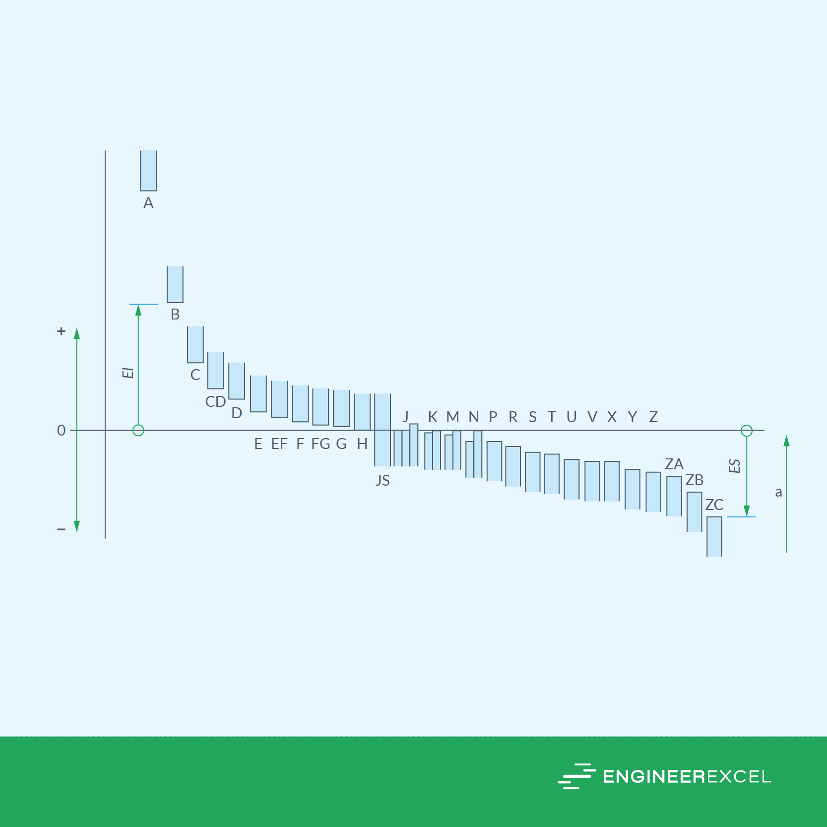
In the diagram above, “El” refers to the lower limit deviation, while “ES” refers to the upper limit deviation.
Observe that the tolerance interval may not always include the nominal size, as limits can be either two-sided or one-sided. In the two-sided case, limits are placed on both sides of the nominal size, while in the one-sided scenario, both limits fall on a single side of the nominal size.
The fundamental deviation values for holes (in micrometers) are shown in the following tables.
H7 Tolerance
Consider H7 tolerance class, which is one of the most commonly used tolerance classes.
For example, when dealing with a hole measuring 40 millimeters, classified under the H7 tolerance class, the toleranced dimension can be expressed in the following manner:
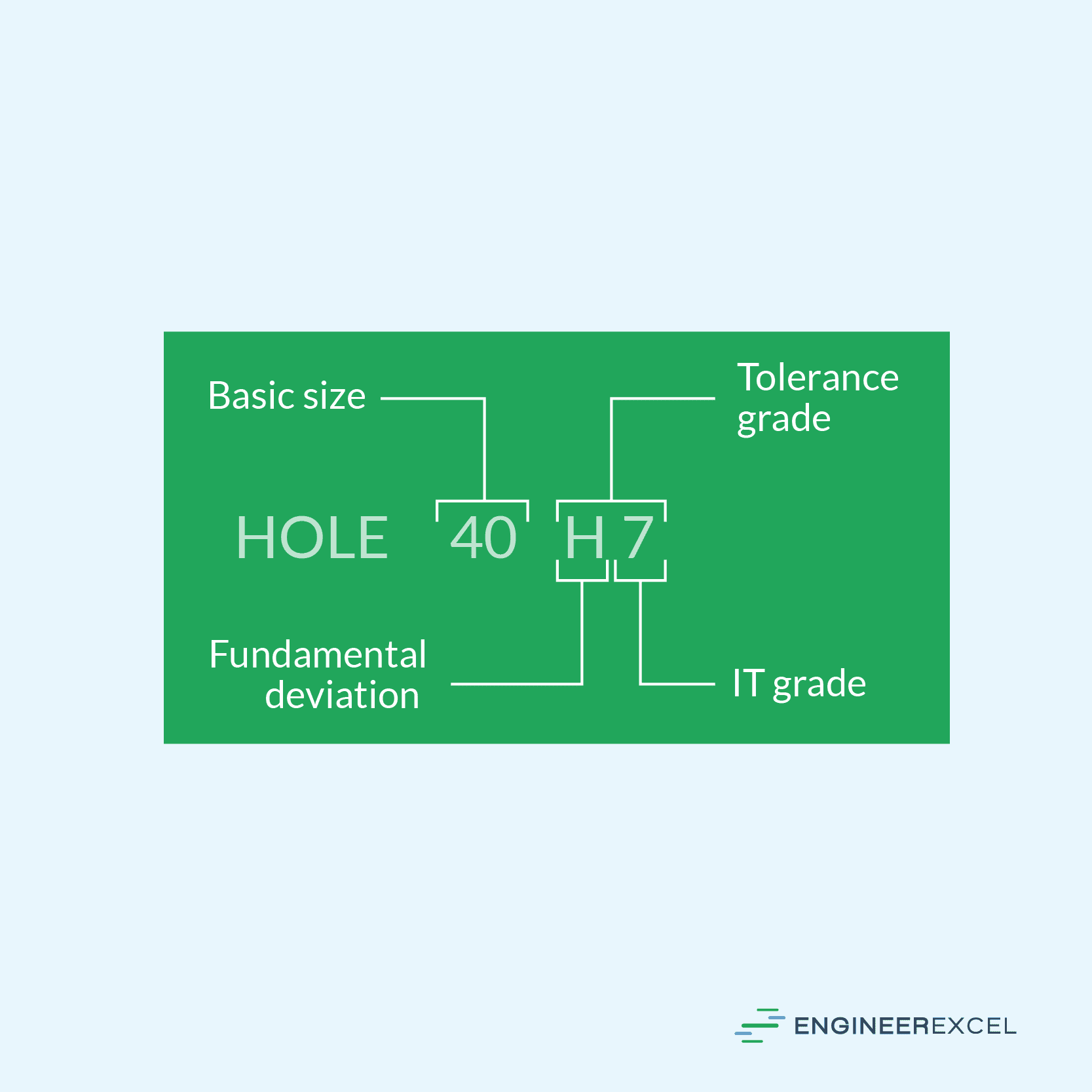
In the figure above, “40” refers to the basic size of the hole in millimeters, “H” refers to the fundamental deviation, “7” refers to the standard tolerance (IT) grade, and “H7” refers to the tolerance class.
Using the tabulated values for standard tolerance grade and fundamental deviation, this hole would have a lower limit deviation of zero and an upper limit deviation of +25 μm.
F7 Tolerance
On the other hand, an F7 tolerance hole of the same size would have a lower limit deviation of +25 μm and an upper limit deviation of +50 μm.
Defining Drill Tolerance Using ISO 14405-1
Another way to define the drill tolerance is using the + and – tolerancing according to ISO 14405-1. Instead of using tolerance classes, ISO 14405-1 indicates the upper and lower tolerance limits as shown in the examples below.
| ISO 286 | ISO 14405-1 |
| 32 H7 | 32 (+0.025,0) |
| 80 JS15 | 80(±0.6) |
Note that both the upper and lower limits can be positive, zero, or negative.
The two tolerancing conventions can also be combined using brackets, as shown in the following example:

Preferred Tolerance Classes
The wide range of tolerance classes offers many choices for limits and fits for hole and shaft combinations. Hence, it is important to restrict the selection of tolerance classes to avoid the unnecessary multiplicity of tools and gauges.
In line with this, the standard prescribes a set of preferred tolerance classes that should be chosen whenever possible. These are boxed in the diagram below.
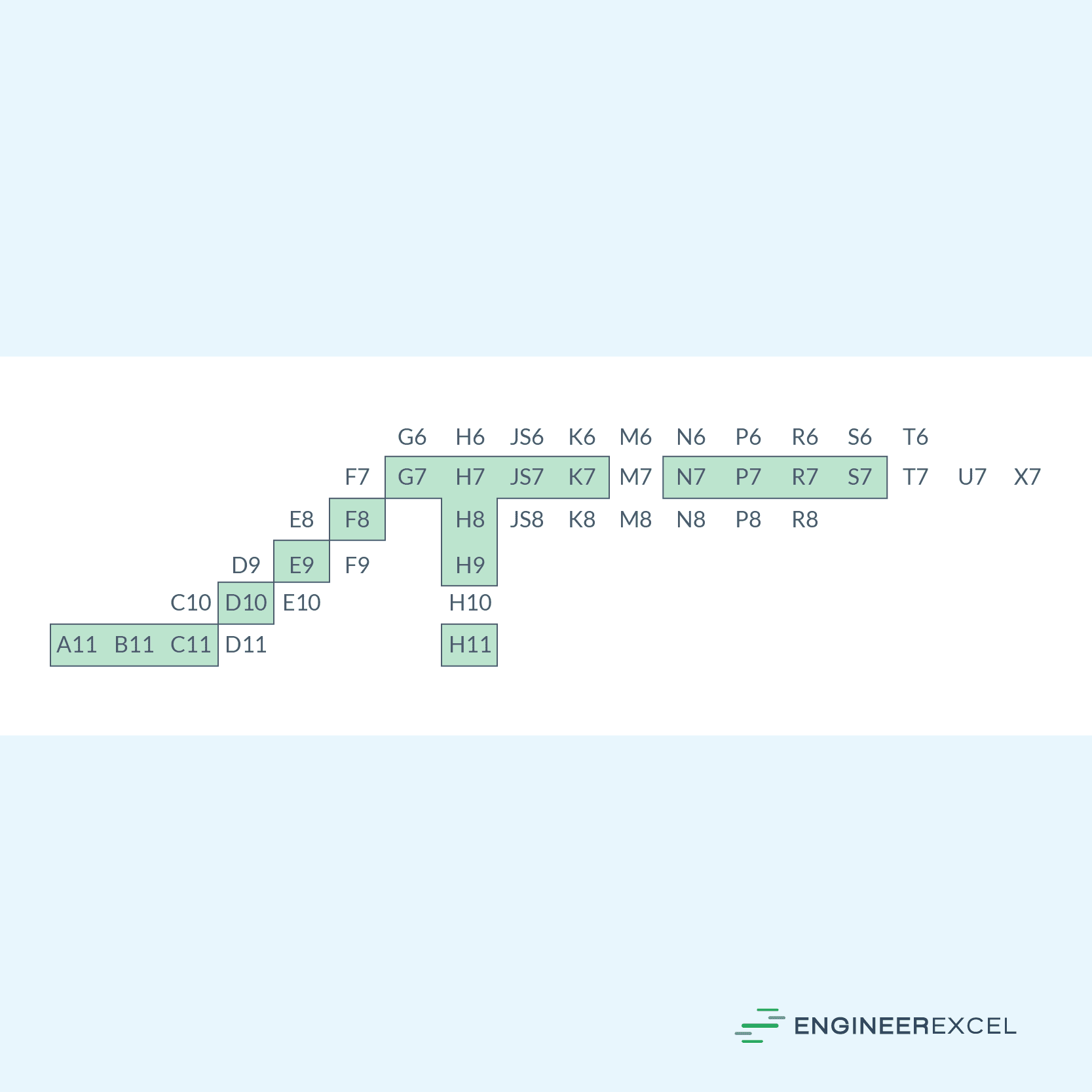
Note that these preferred tolerance classes are only applicable to general purposes. Some applications, like keyways, require a more specialized selection of tolerance classes.
Types of Fits
Ultimately, the choice of the appropriate tolerance class for a drilled hole depends on the desired type of fit in conjunction with a shaft. There are three primary types of fits: clearance fit, interference fit, and transition fit.
A clearance fit ensures that there is always space between the hole and the shaft when they are assembled. In other words, the smallest permissible hole size is always larger than or equal to the largest permissible shaft size.
Conversely, when assembled, an interference fit guarantees a tight connection between the hole and the shaft. Here, the largest permissible hole size is always smaller than or equal to the smallest permissible shaft size.
Lastly, a transition fit allows for clearance or interference between the hole and the shaft upon assembly.
Fits can be specified either as shaft-basis or hole-basis, depending on which part’s dimensions are controlled to determine the fit. The hole size remains constant in a hole-basis system while the shaft diameter varies to achieve the fit. Conversely, the shaft size remains constant in a shaft-basis system while the hole diameter varies to achieve the fit.
The hole-basis fit system is commonly used for general applications. On the other hand, the shaft-basis fit system should be employed only where it offers economic advantages.
ISO 286 provides a set of preferred combinations of hole and shaft tolerance classes for different fits. These combinations are boxed in the diagrams below.
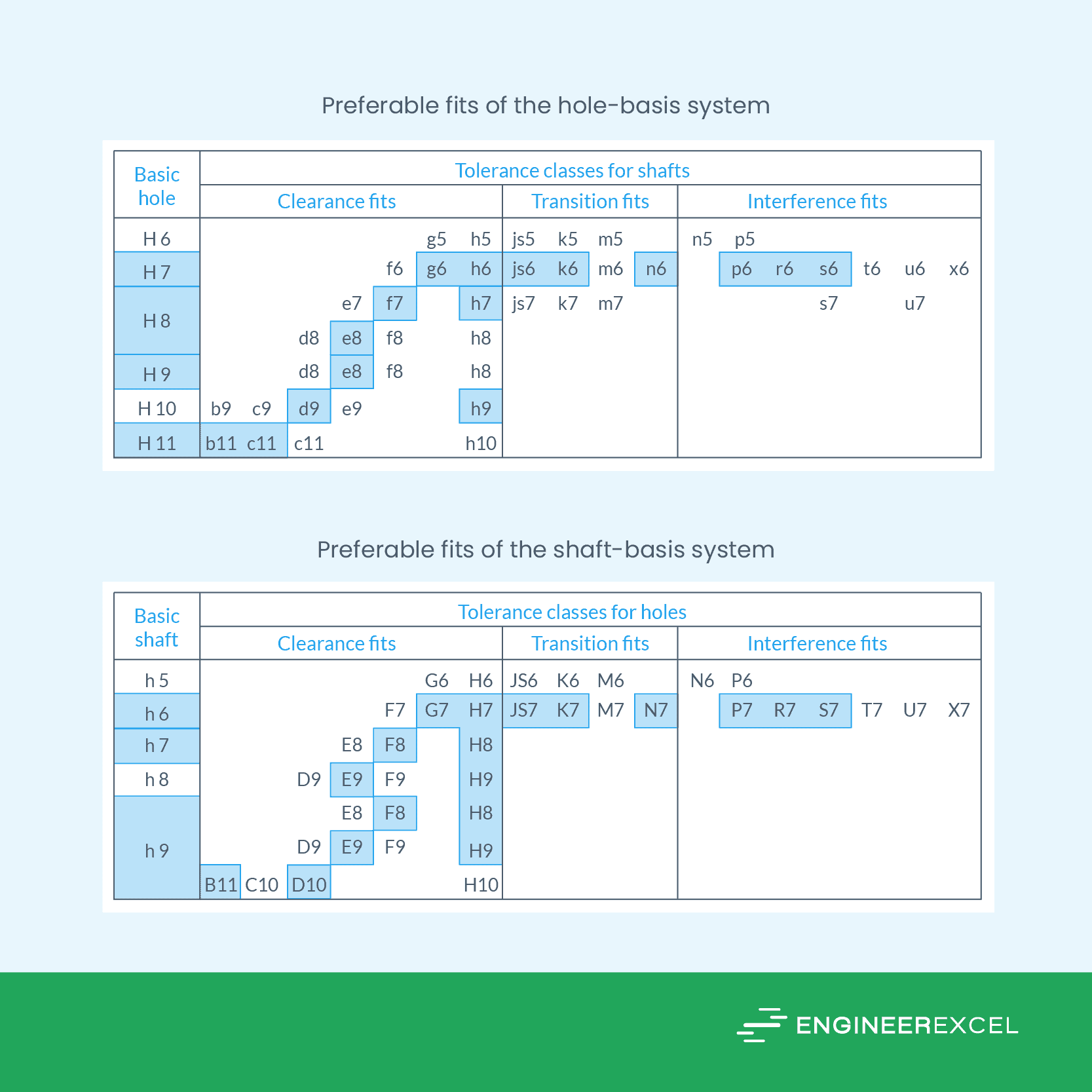
The combinations listed above should generally be able to cover the requirements for typical engineering applications. However, in certain specialized cases, it may be necessary to manually calculate the permissible clearance or interference based on the functional requirements of the mating parts, and then transform these calculations into limit deviations.