
Fluid flow in both circular and noncircular pipes are commonly encountered in various practical applications such as domestic water systems, oil and gas piping networks, and hydronic space heating systems. When designing these systems, two crucial parameters come into play: flow rate and pressure within the pipes.
This article delves into the fundamental concepts of pipe flow rate and pressure, and explores their differences, relationship, and impact on the overall design of piping systems.
Pipe Flow Rate vs Pressure
Pipe pressure and flow rate are closely related concepts that both characterize the behavior of fluid in a piping system.
Pipe flow rate refers to the amount of fluid that flows through a pipe per unit of time. This flow rate may refer to the mass of the fluid passing through the pipe, which is known as the mass flow rate, or to the volume of the fluid, known as the volumetric flow rate.
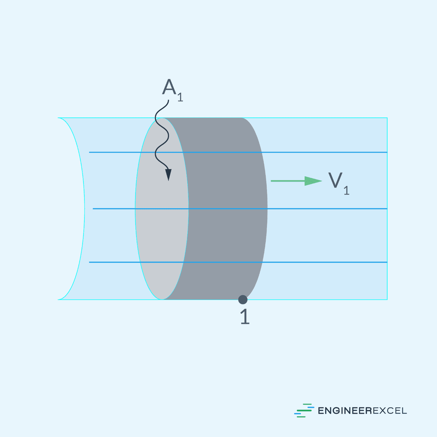
Consider an incompressible fluid flowing through a pipe at a constant mean velocity, as shown in the diagram below. The flow within the pipe is fully developed, meaning it has reached a stable state, and the cross-sectional area of the pipe remains constant along its length.

Elevate Your Engineering With Excel
Advance in Excel with engineering-focused training that equips you with the skills to streamline projects and accelerate your career.
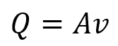
The volumetric flow rate can be calculated using the formula:
Where:
- Q = volumetric flow rate of an incompressible fluid [m3/s]
- A = cross-sectional area of the pipe [m2]
- v = mean velocity of the fluid flow [m/s]
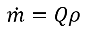
From the volumetric flow rate, the mass flow rate can be calculated using the formula:
Where:
- ṁ = mass flow rate [kg/s]
- ρ = density of the fluid flowing through the pipe [kg/m3]
Pipe pressure, on the other hand, represents the force exerted on a fluid particle within a pipe from all directions. It is commonly measured using gauges affixed to the side of a pipe.
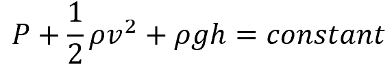
Ignoring head losses due to friction, fittings, and other components, the simplest way to relate pressures at different points in a piping network is through Bernoulli’s equation, which can be mathematically expressed as:
Where:
- P = pressure at any point of a piping network [Pa]
- g = acceleration due to gravity [9.81 m/s2]
- h = elevation at the specified point [m]
In essence, Bernoulli’s principle states that a decrease in the static pressure of a fluid occurs simultaneously with an increase in the fluid’s velocity or a decrease in its potential energy. This can be derived from the principle of conservation of energy. It is important to note that this equation is applicable only to fluids with constant density, steady flow, and without any viscous forces and frictional losses.
In practical applications, however, calculating the pressure is much more complex. Aside from variations in fluid properties, pressure within a piping system may vary due to factors such as changes in elevation, frictional losses, and pressure drops caused by the different components including fittings, valves, and pumps.
Pressure regulators and gauges are typically installed to monitor and control system pressure. In general, piping systems operate at different pressure levels depending on application. This is because different processes require varying levels of pressure to function.
For example, huge industrial processes such as power generation, chemical manufacturing, or oil refining often involve high-pressure systems to achieve desired fluid state or properties. On the other hand, water supply systems or irrigation networks often operate at lower pressures to avoid damaging components, improve safety, and minimize energy consumption and operational costs.
Relationship Between Pipe Flow Rate and Pressure
Determining the flow rate of a pipe solely based on the pressure at a single point, or vice versa, is not possible. The pressure at a single point does not provide sufficient information to estimate the flow rate accurately. Instead, the parameter more closely associated with flow rate is the pressure drop, which is the difference in pressure between two points along a pipe.
If all other factors are equal, a higher pressure drop results in a greater flow rate. This occurs because a larger pressure difference between two points in the pipe creates a stronger driving force for the fluid to move.
However, it is important to note that other factors like pipe configuration and geometry, fluid properties, and flow regime also impact the flow rate. Hence, while a higher pressure drop suggests a higher flow rate, it should not be viewed as the only determining factor.
Calculating Pipe Pressure Drop from Flow Rate
To calculate the pressure drop in a pipe, it is necessary to consider the potential sources of head loss within the piping system.
Pressure Drop Due to Friction
For a fully developed horizontal internal fluid flow with no obstructions, the pressure drop across two points is primarily caused by friction. In this case, the pressure drop due to friction can be calculated using the Darcy-Weisbach equation:
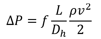
Where:
- ΔP = pressure drop due to friction across two points separated by distance L [Pa]
- f = Darcy-Weisbach friction factor [unitless]
- L = pipe length or distance between the two points [m]
- Dh = hydraulic diameter of the pipe [m]
Knowing that the mean fluid velocity is simply the quotient of the volumetric flow rate and cross-sectional area, the above equation can be transformed into:
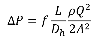
This equation establishes a relationship between the pressure drop and volumetric flow rate for a pipe flow where the only factor causing head loss is friction. Regardless of whether the flow is laminar or turbulent, through circular or non-circular pipes, or through horizontal or inclined pipes, this formula for calculating pressure drop due to friction remains valid.
Note that, for non-circular pipes, the hydraulic diameter is a parameter used to characterize the effective cross-sectional area of an equivalent circular conduit that would exhibit the same hydraulic resistance. This can be calculated using the formula:
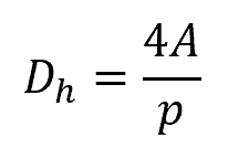
Where:
- p = wetted perimeter of the pipe’s cross-sectional area [m]
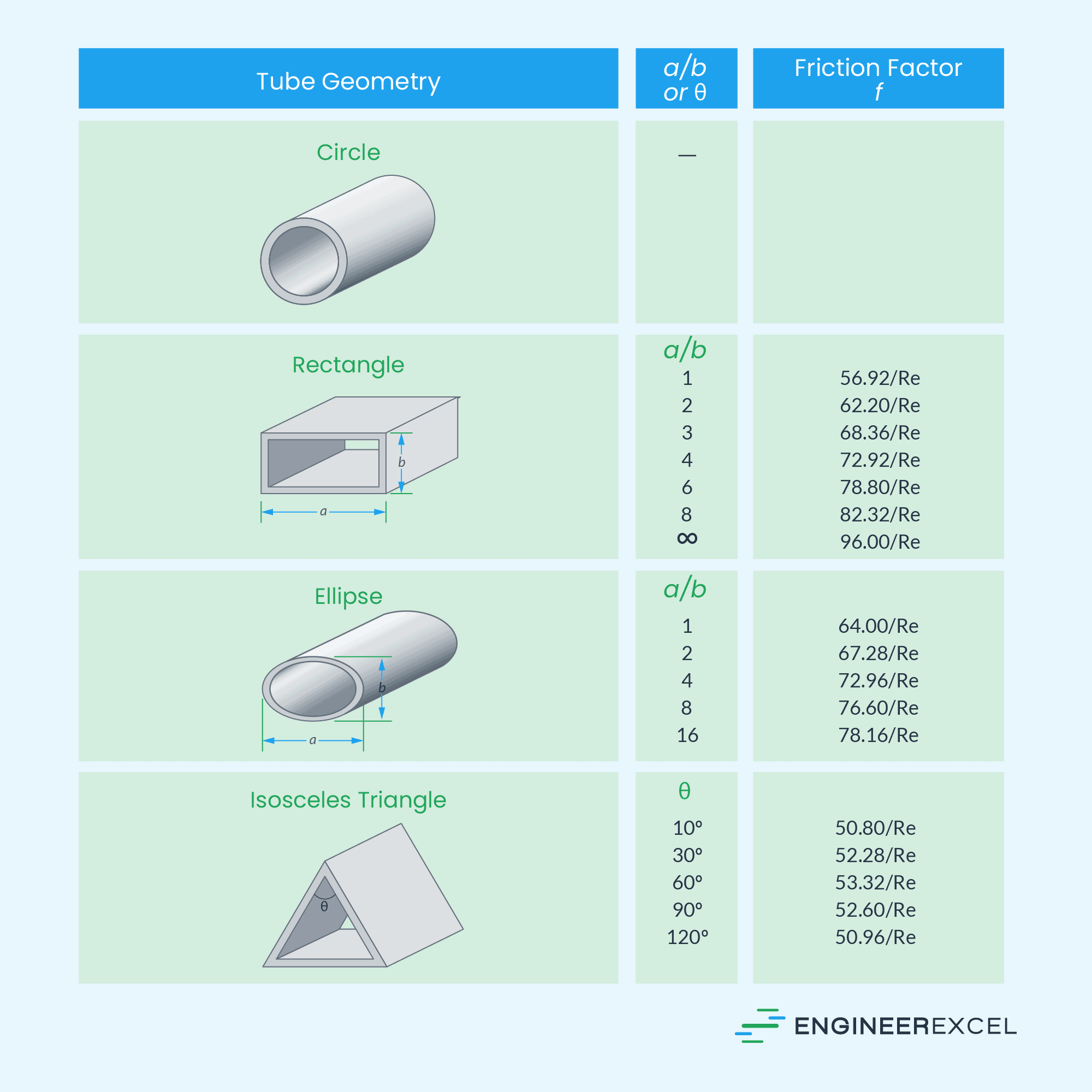
Furthermore, the value of the friction factor, f, depends on the flow regime, which is primarily dependent on Reynolds number, Re. In practical conditions, the flow in a circular pipe is laminar for Re ≤ 2300, turbulent for Re ≥ 4000, and transitional in between.
The table below displays the friction factors for fully developed laminar flow in pipes of different cross sections.
For fully developed turbulent flow, the value of the friction factor depends on both the Reynolds number and the relative roughness of the pipe. These can be implicitly related using the Colebrook equation:
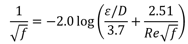
The relative roughness, ε/D, is simply the ratio between the mean height of roughness of the pipe material to the pipe diameter.
To simplify the determination of the friction factor value for fully developed flow in circular tubes, Lewis F. Moody drew the relationship between the friction factor, Reynolds number, and relative roughness in a diagram called the Moody Chart. Although it is originally developed for circular pipes, it can also be used for noncircular pipes by using hydraulic diameter.
The Moody Chart is shown in the figure below.
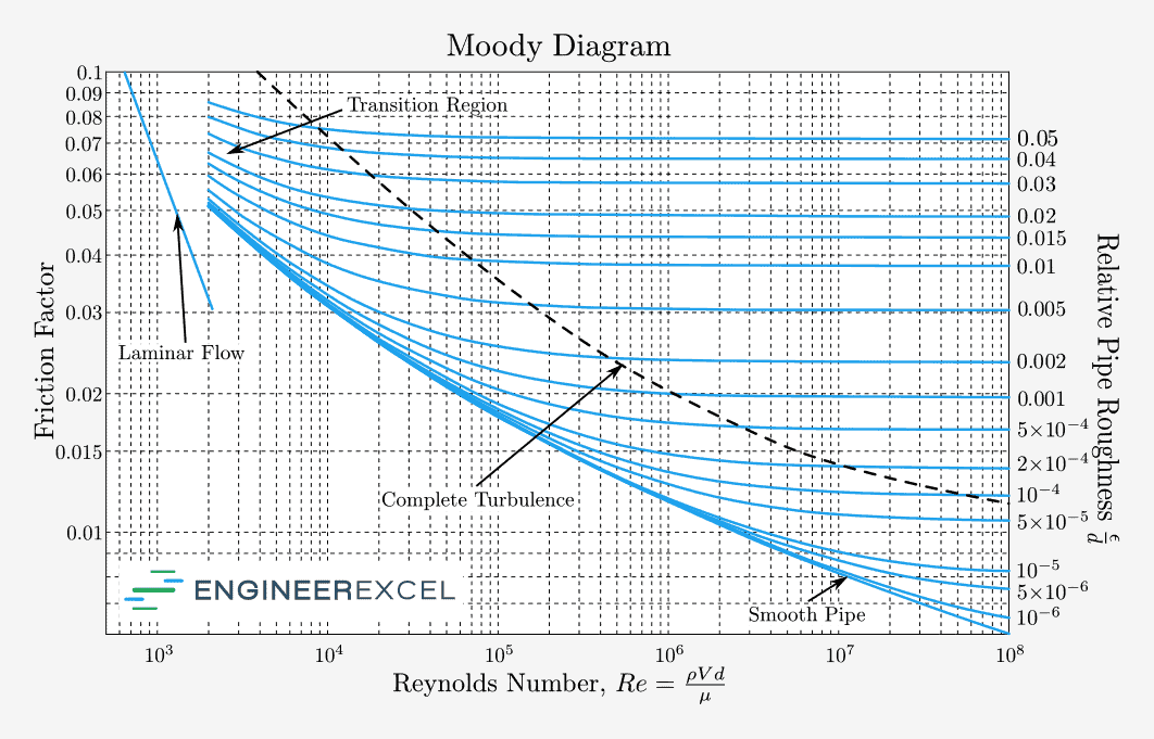
The friction factor in the transition region between the laminar and turbulent regimes (2300 ≤ Re ≤ 4000) may alternate between the values for laminar and turbulent flow. Hence, the data in this range are the least reliable.
Pressure Drop in Inclined Pipes
In inclined pipes, the force of gravity becomes a significant factor in addition to viscous forces when considering the balance of forces. As a result, the combined effect of pressure difference and gravity influences the flow.
Gravity assists with downhill flow while opposing uphill flow. Hence, uphill flow requires a considerably higher pressure difference to sustain a specific flow rate.
In this case, the volumetric flow rate and pressure drop can be mathematically related using the formula:
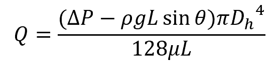
Where:
- θ = angle of the inclined pipe [degrees or radians]
- μ = viscosity of the fluid [P]
Note that θ > 0 for uphill flow, and θ < 0 for downhill flow.
Pressure Drop Due to Valves and Fittings
In practical piping systems, fluid flow encounters different piping components such as fittings, valves, enlargements, and contractions. These elements disrupt the smooth flow of the fluid, leading to additional losses due to flow separation and mixing. These losses are commonly referred to as minor losses.
These minor losses are quantified using loss coefficients, allowing the total head loss to be calculated as the sum of the frictional major and minor losses. The mathematical expression below illustrates this relationship.
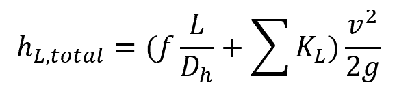
Where:
- hL,total = total head loss of the piping system [m]
- KL = loss coefficient of each piping component [unitless]
Converting the head loss and mean velocity variables into pressure drop and volumetric flow rate, respectively, the equation above can be transformed into:
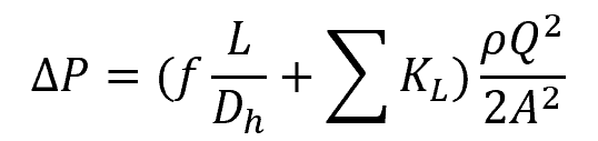
The loss coefficients of some of the most common components of minor losses are listed in the tables below.


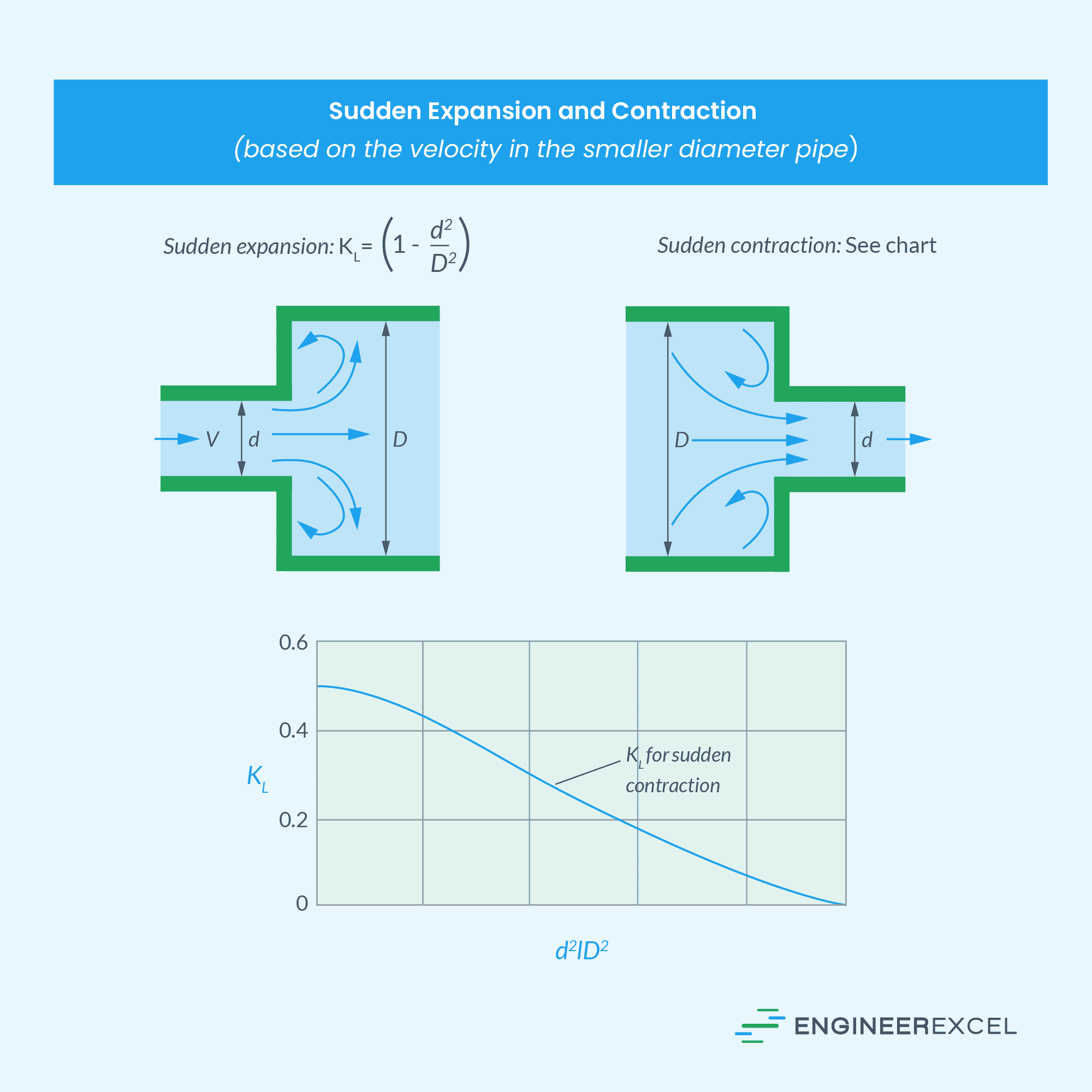
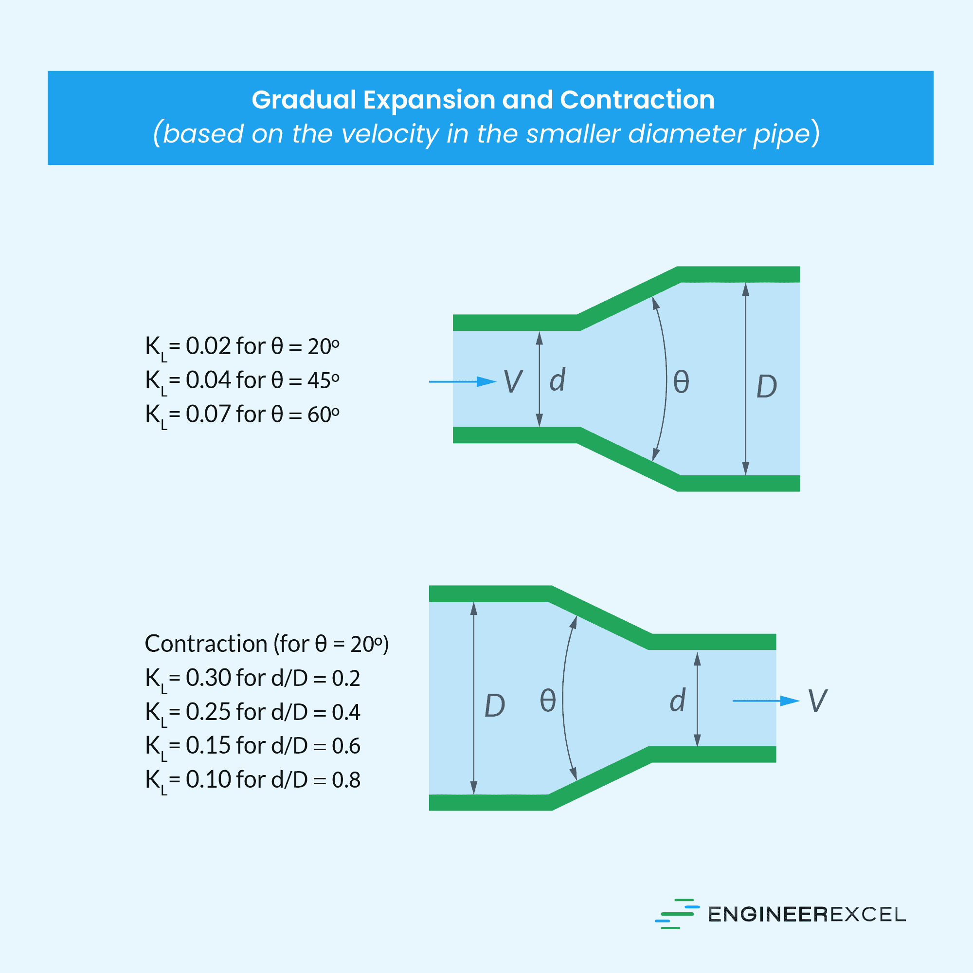
Note that these are only estimated loss coefficient values. Actual values strongly depend on the design and manufacture of the components.