
Pipe diameter, pressure, and flow are essential parameters that affect the behavior of fluid in a pipe. Hence, understanding how these variables affect each other is important in designing efficient piping systems.

This article tackles the basic principles and formulas that govern the relationship between pipe diameter, pressure, and flow, and how they can be applied in piping design.
Pipe Diameter vs. Pressure vs. Flow
Before delving into the relationship between pipe diameter, pressure, and flow, it is important to first define these terms.
In the context of fluid mechanics, pipe diameter refers to the inner width of a pipe. It is typically measured in millimeters (mm) or inches (in), with its value dependent on the nominal pipe size.

Elevate Your Engineering With Excel
Advance in Excel with engineering-focused training that equips you with the skills to streamline projects and accelerate your career.
Pressure refers to the force per unit area that the fluid exerts on the pipe walls. It is typically measured in pounds per square inch (psi) or Pascals (Pa). When examining pipe flow, the focus is often on the pressure difference between two distinct points along the pipe, instead of the absolute pressure inside the pipe.
Flow describes the movement of fluid within the pipe. In the design of piping systems, fluid flow can be characterized by either flow velocity or flow rate.
Flow velocity refers to the speed at which the fluid travels through the pipe, measured in meters per second (m/s) or feet per second (ft/s). On the other hand, flow rate quantifies the volume of fluid passing through the pipe per unit of time.

Flow rate can be measured using volumetric flow rate, expressed in cubic meters per second (m³/s), gallons per minute (gpm), or liters per second (L/s). Alternatively, it can be measured using mass flow rate, expressed in kilograms per second (kg/s) or pounds per second (lb/s).
Effect Of Pipe Diameter On Flow Rate
The larger the diameter of the pipe, the greater the flow rate, assuming a constant flow velocity. This is because larger diameter means a wider cross-sectional area available for the fluid to flow through. Conversely, in a smaller diameter pipe, the flow rate would be lower for the same flow velocity.
This relationship is described by the principle of conservation of mass, which states that the mass of fluid entering a section of pipe must be equal to the mass of fluid exiting that section. This principle leads to the continuity equation, as shown in the following equation:
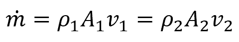
Where:
- ṁ = mass flow rate [kg/s]
- ρ1, ρ2 = density of fluid at two different points [kg/m3]
- A1, A2 = cross-sectional area of the pipe at two different points [m2]
- v1, v2 = fluid velocity at two different points [m/s]
For a circular pipe, the formula above can be transformed into:
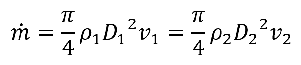
Where:
- D1, D2 = diameter of the pipe at two different points [m]
Effect Of Pipe Diameter On Pressure
The relationship between pipe diameter and pressure is guided by Bernoulli’s principle. To illustrate, consider the diagram below demonstrating the flow of a fluid through a constriction.
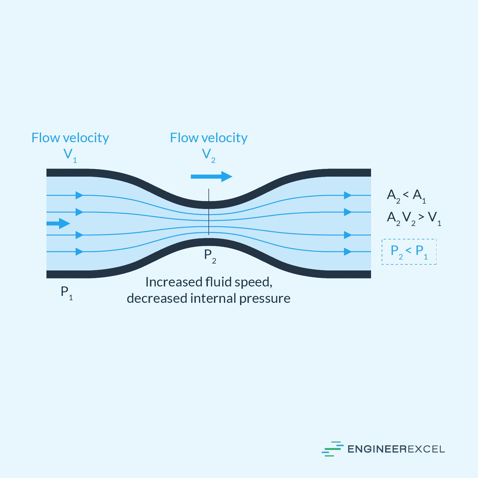
As the pipe’s diameter and cross-sectional area decrease, the fluid’s velocity increases, leading to a decrease in pressure. Conversely, when the pipe’s diameter increases, the fluid’s velocity decreases, resulting in an increase in pressure. This phenomenon occurs because the fluid must maintain mass and energy conservation while moving through the pipe, as depicted in the Bernoulli equation below:
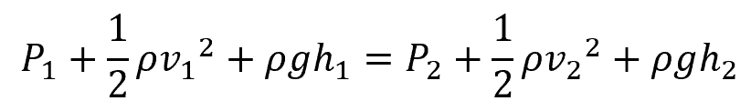
Where:
- P1, P2 = internal pressure at two different points [Pa]
- h1, h2 = height of pipe at two different points [m]
- g = gravitational constant [9.81 m/s2]
Note that this relationship is typically nonlinear because there are other factors that affect pipe pressure, not just pipe diameter. These factors include the viscosity of the fluid and the roughness of the pipe’s inner wall.
Effect Of Pressure On Flow Rate
Instead of looking only at the absolute pressure, it is the pressure difference between two points along the pipeline that directly affects the magnitude of the flow rate. The impact of the pressure difference on the flow rate depends on the type of flow and the fluid’s properties.
Generally, the greater the pressure difference, the greater the flow rate. This is because a larger pressure difference results in a greater force driving the fluid through the pipe, overcoming the resistance or frictional losses. Conversely, the lesser the pressure difference, the lower the flow rate.
Calculating Flow From Pipe Diameter And Pressure
There are several methods that can be used to calculate flow from pipe diameter and pressure, depending on the flow regime. This section tackles two of the most widely used formulas: the Darcy-Weisbach equation and Poiseuille’s Law.
Calculating Flow Using Darcy-Weisbach Equation
Using the Darcy-Weisbach equation, flow rate can be derived from fluid velocity, which can be calculated from the pressure difference across two points, as shown in the following formula:
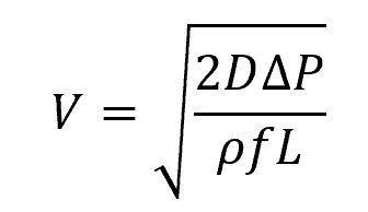
Where:
- V = fluid velocity [m/s]
- ΔP = pressure difference across two points along the pipeline [Pa]
- f = Darcy-Weisbach friction factor [unitless]
- L = length of pipe [m]
- D = hydraulic diameter of the pipe [m]
Knowing that the volumetric flow rate is simply the product of the fluid velocity and cross-sectional area of the pipe, the formula above can be transformed into:
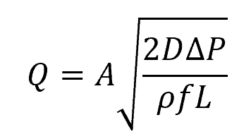
Where:
- Q = volumetric flow rate [m3/s]
- A = cross-sectional area of the pipe [m2]
This equation is applicable to various pipe flow conditions, including laminar and turbulent flow, as well as smooth or rough pipe surfaces, whether the pipes are oriented horizontally or inclined under pressure. The equation is based on the assumption that pressure losses are primarily attributed to friction.
The Darcy-Weisbach friction factor is a dimensionless parameter that is used to characterize the frictional losses in fluid flow through pipes. Its value depends on various factors, including the Reynolds number, which characterizes the flow regime, and the roughness of the pipe’s internal surface. The friction factor is typically obtained from empirical correlations or using the Moody chart.
Calculating Flow Using Poiseuille’s Law
Another equation that allows for the calculation of flow rate based on pressure difference and pipe size is known as Poiseuille’s Law. According to this law, the laminar flow rate for an incompressible fluid through a pipe is directly proportional to the fourth power of the pipe’s radius (or half of the diameter). This relationship is expressed by the following equation:
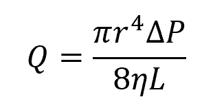
Where:
- r = pipe radius [m]
- η = fluid viscosity [Pa-s]
Note that Poiseuille’s Law can only be used for incompressible fully-developed laminar flows in horizontal circular pipes. This equation assumes that pressure losses are only due to the viscous effect of the fluid.