
As fluid flows through pipe fittings such as elbows, valves, and tees, some of the energy is lost due to friction, turbulences, and sudden changes in flow direction. In fluid mechanics, these losses are quantified using a dimensionless parameter called the loss coefficient.
Understanding and calculating the loss coefficient for various pipe fittings plays a significant role in designing efficient and effective fluid transport systems.
Loss Coefficient for Pipe Fittings
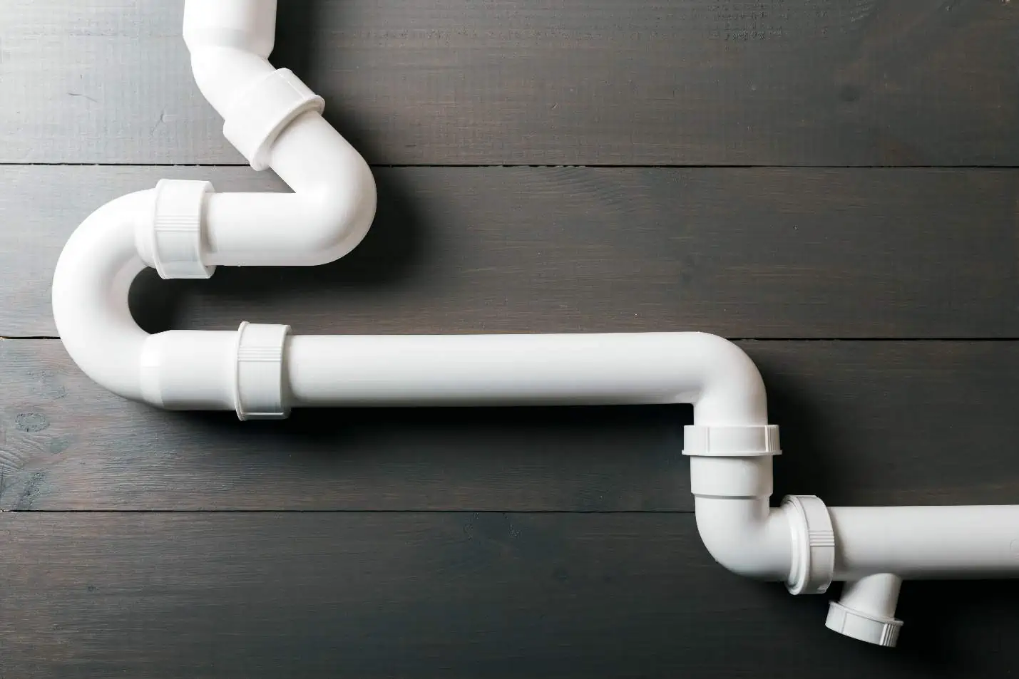
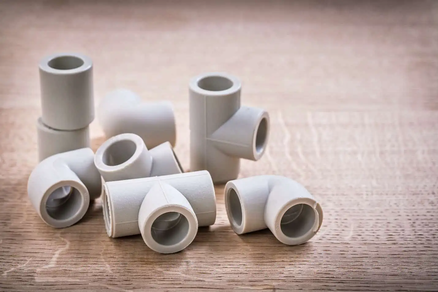
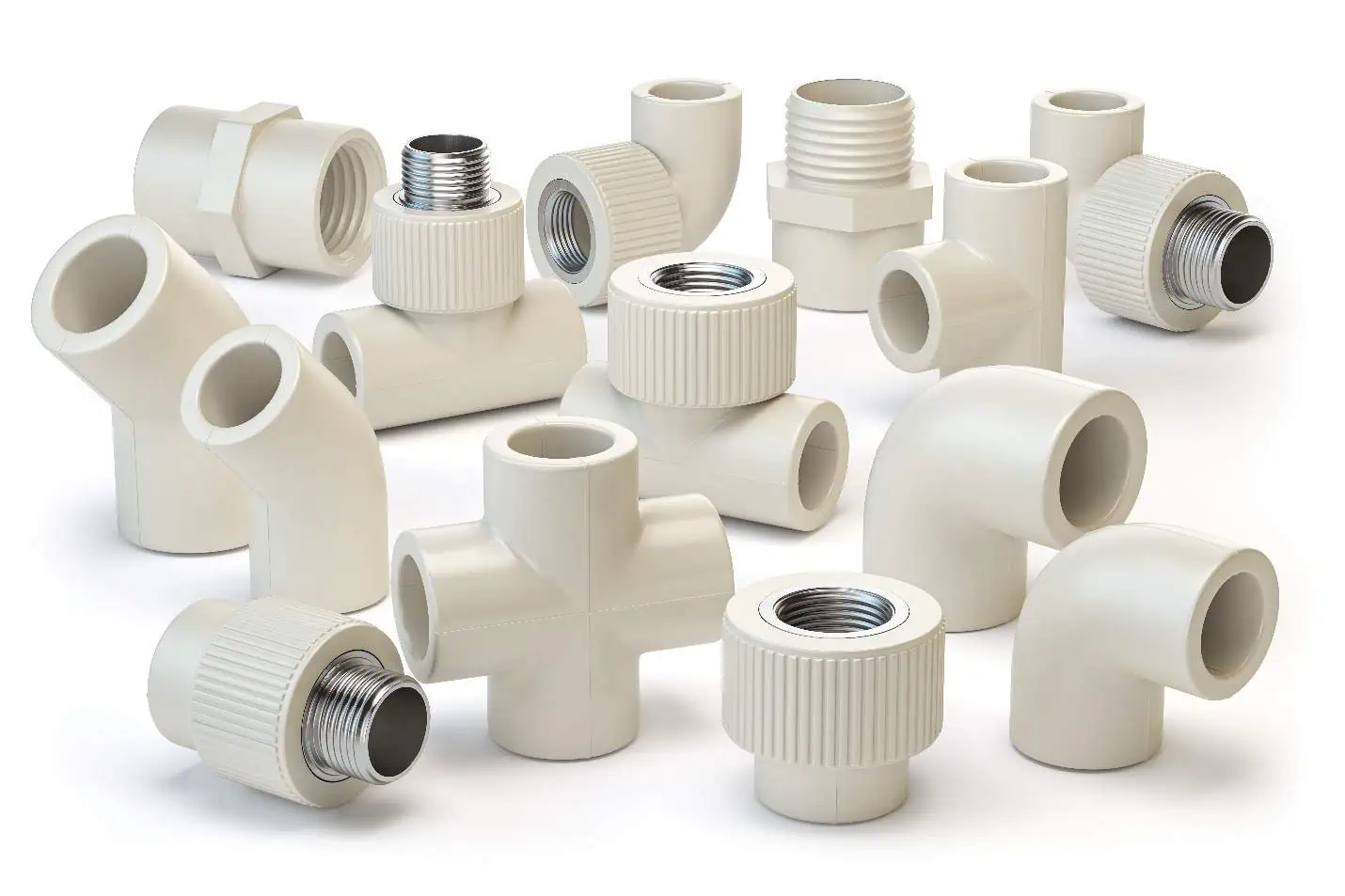
Pipe fittings are components used to connect, divert, or join sections of pipes within a fluid flow system. They come in various shapes, sizes, and materials, and are used in a wide range of industries, including plumbing, oil and gas, and construction.

Elevate Your Engineering With Excel
Advance in Excel with engineering-focused training that equips you with the skills to streamline projects and accelerate your career.
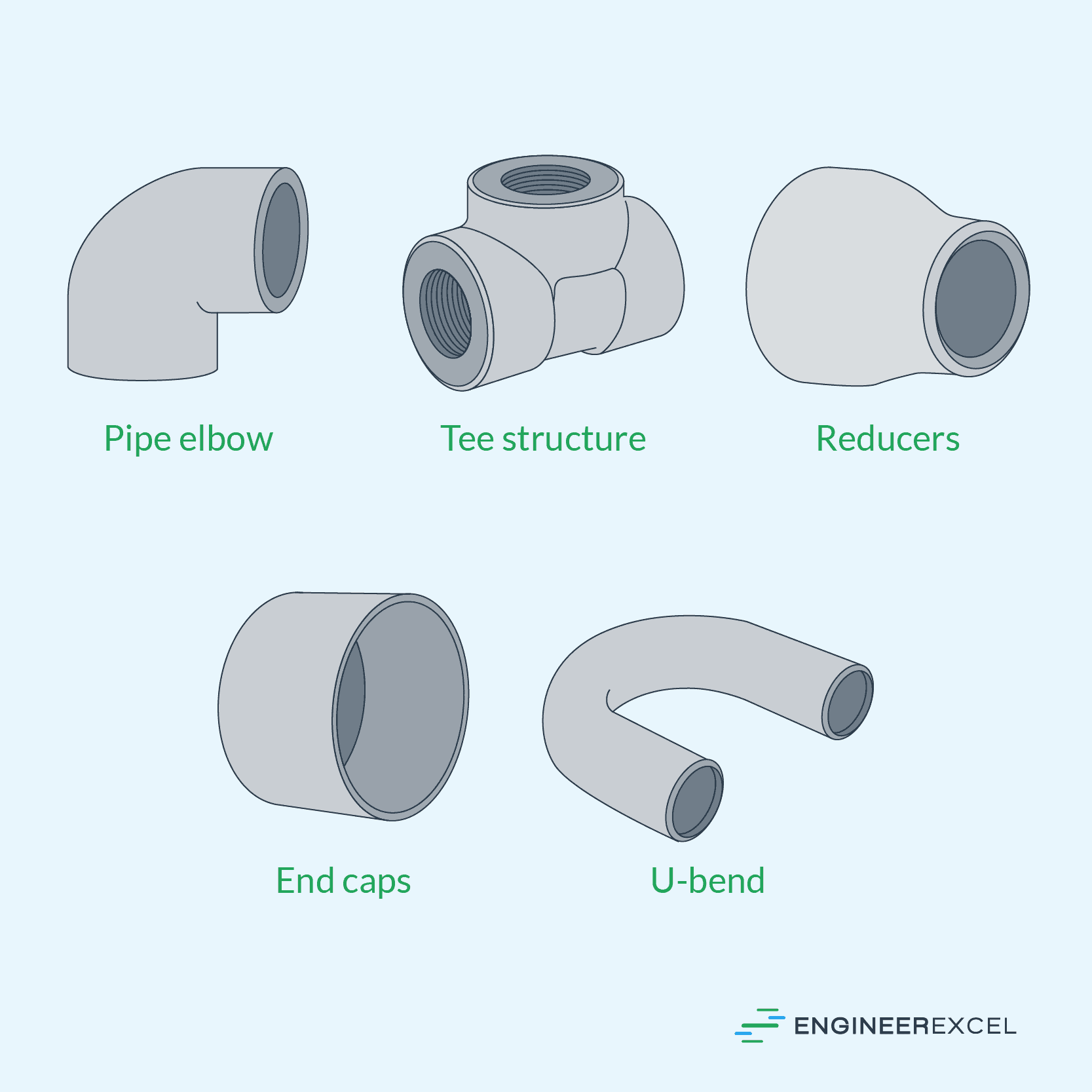
Some common types of pipe fittings include elbows, tees, couplings, reducers, and flanges. These fittings are typically made from materials such as steel, brass, copper, PVC, and plastic, and are designed to withstand high pressure and temperature conditions.
Just like any other pipe component, pipe fittings introduce pressure and energy losses in the system. These losses are normally quantified using loss coefficients.
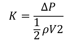
The loss coefficient in pipe fittings is a measure of the energy loss that occurs when fluid flows through a fitting due to friction and changes in fluid flow direction. It is a dimensionless parameter that represents the ratio of the head loss across the fitting to the dynamic pressure of the fluid, as shown in the following equation:
Where:
- K = loss coefficient of the pipe fitting [unitless]
- ΔP = pressure drop due to the fitting [Pa]
- ρ = fluid density [kg/m3]
- V = fluid velocity [m/s]
The value of the loss coefficient is influenced by various factors such as the size and shape of the fitting, the Reynolds number of the fluid, and the flow rate. It is used in fluid dynamic calculations to determine the pressure drop and flow rate through a pipeline system. Hence, accurate estimation of loss coefficients is important for designing efficient piping systems and optimizing fluid flow.
Calculating Head Loss from Loss Coefficients
Once you obtain the loss coefficient values, the total head loss due to pipe fittings can be calculated using the following formula:
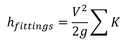
Where:
- hfittings = total head losses due to the fittings [m]
- ∑K = summation of the fittings’ loss coefficients [m]
- g = gravitational constant [9.81 m/s2]
It’s worth noting that, in addition to losses caused by pipe fittings, other components such as valves, contractions, expansions, inlets, exits, and the pipe itself can also contribute to losses. These losses are typically combined to determine the total head losses in the system. Determining the total head loss is crucial for achieving an efficient design and ensuring proper operation of your piping network.
Loss Coefficient Values of Different Pipe Fittings
Creating an accurate list of loss coefficients can be challenging as values may vary between manufacturers and change with advancements in fitting fabrication technology. For instance, modern forged and molded fittings typically have lower loss coefficients than older designs. Thus, it is always recommended to use updated and precise data provided by the manufacturer, if available.
However, to provide a general approximation, the averaged loss coefficient values from various manufacturers are listed in the following tables, which may result in an uncertainty of up to ±50 percent.
Loss Coefficient of Elbows
Elbows are a type of fitting used to change the direction of fluid flow in one direction. The loss coefficient of an elbow depends on factors like its angle, radius, and pipe diameter.
The table below shows the loss coefficients of different types of elbows at different nominal diameters.
Screwed
Flanged
Notice that the loss coefficient value generally decreases with increasing pipe size. In addition, the type of connection, whether screwed or flanged, also affect its value.
Loss Coefficient of Tees
Tees are fittings that split or combine fluid flow. The primary flow which passes straight through a tee typically has a lower loss coefficient value compared to the flow that takes the branch. These are listed in the table below.
Screwed
Flanged
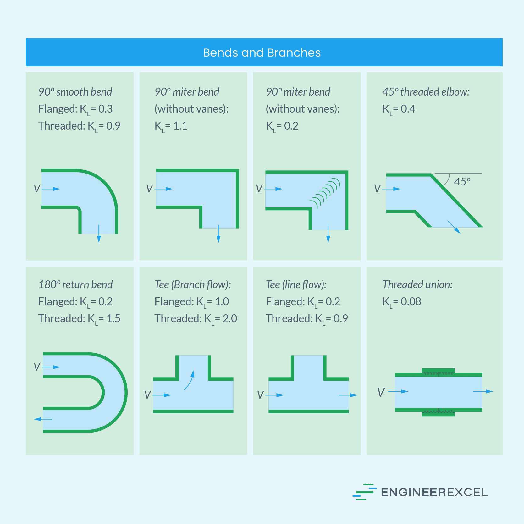
Loss Coefficient of Bends and Branches
Bends are smooth and gradual changes in the direction of flow with no sharp corners. They are typically manufactured in 45⁰ or 90⁰ curvature, although there can also be custom angles. They usually have lower loss coefficient values compared to elbows since they minimize flow resistance.
On the other hand, branches are tee-shaped connections that split the main pipeline into two or more smaller pipelines. This allows the fluid to be distributed to different directions or locations.
The table below shows the typical values of loss coefficients for some of the most common configurations of bends and branches.
Determining Loss Coefficient for Pipe Fittings
In general, the loss coefficient values can be obtained from manufacturer’s data or engineering handbooks. However, in the absence of accurate data, the loss coefficient for a pipe fitting can be determined either by experimental or theoretical approach.
The experimental approach involves setting up a test rig with the pipe fitting to be tested, a pump, a flow meter, and pressure sensors. The pressure drop across the fitting and the flow rate of the fluid are measured, and the Reynolds number of the fluid is calculated to determine the flow regime.
The experiment is repeated for different flow rates and Reynolds numbers, and the pressure drop is plotted against the dynamic pressure of the fluid. The data is then fit to a curve, and the loss coefficient is calculated using the curve-fit equation.
On the other hand, the theoretical approach involves using empirical equations that are based on experimental data to estimate the loss coefficient for a given fitting under specific flow conditions. The accuracy of the empirical equations depends on the range of flow rates and Reynolds numbers used to develop the equation.
Theoretical calculations can also be performed using computational fluid dynamics (CFD) simulations to determine the loss coefficient. CFD simulations use numerical methods to solve the governing equations of fluid flow and can provide detailed information on the flow field and pressure distribution.