
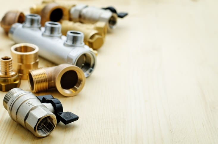
Pipe fittings including tees, elbows, bends, couplings, and valves contribute a substantial amount of pressure loss in a piping system. Hence, it is important to take them into account during the design process in order to properly size the motors and pumps needed to transport the process fluid within the system. One way to estimate this pressure loss is by obtaining the Equivalent Length of Pipe Fittings.
Calculating The Equivalent Length Of Pipe Fittings
By definition, the equivalent length of a fitting is the length of a similarly-sized straight pipe that would yield the same pressure drop at the same flow rate. In doing piping calculations, the equivalent lengths of all components are added to the total pipe length before using the Hazen-Williams Equation or the Darcy-Weisbach Formula to calculate the total pressure loss.
Before learning how to calculate the equivalent length of pipe fittings, it is important to understand the different types of pressure losses in a piping system.
As fluid flows within a piping system, it incurs pressure losses caused by flow resistance along the network of pipes, fittings, and valves. These losses are categorized into two types: major losses and minor losses.

Elevate Your Engineering With Excel
Advance in Excel with engineering-focused training that equips you with the skills to streamline projects and accelerate your career.
Major losses refer to pressure losses incurred along straight pipes caused by both the internal friction within the fluid (i.e., its viscosity) and the friction between the fluid and the pipe wall. On the other hand, minor losses refer to the additional losses incurred across components like fittings and valves, usually induced by curvature or recirculation.
Hence, obtaining the equivalent length of pipe fittings is like converting minor losses into an equivalent major loss.
The minor loss of a fitting can be calculated using the formula:
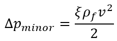
Where:
- ξ = minor loss coefficient of the fitting [unitless]
- ρf = fluid density [kg/m3]
- v = fluid velocity [m/s]
On the other hand, the major loss can be calculated using the formula:
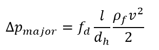
Where:
- fd = Darcy friction factor of the fluid flow inside the pipe connected to the fitting [unitless]
- l = length of pipe [m]
- dh = hydraulic diameter [m]
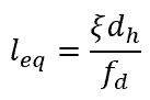
Equating the two losses, the formula for the equivalent length of a pipe fitting results to the following equation:
The minor loss coefficient is a dimensionless value normally obtained based on experiments, while the friction factor can be estimated using the Moody Diagram or the Colebrook equation.
Minor Loss Coefficients Of Common Fittings: ASHRAE
ASHRAE, or the American Society of Heating, Refrigerating and Air-Conditioning Engineers, publishes a table of minor loss coefficients for common fittings. Based on the ASHRAE Fundamentals Handbook, the minor loss coefficients of some of the most common fittings are listed below.
Minor Loss Coefficients of Common Screwed Pipe Fittings
Minor Loss Coefficients of Common Flanged Welded Pipe Fittings
It should be noted that the minor loss is predominantly affected by the fitting’s geometry and its impact on the fluid movement. The material used for the fitting as well as the fluid properties only has little effect on the pressure drop.
Therefore, a plastic tee will almost have the same pressure drop as a steel tee with the same geometry. However, since the major loss is strongly affected by the friction factor, the equivalent length will also be affected by the roughness of the pipe the fitting is connected with.
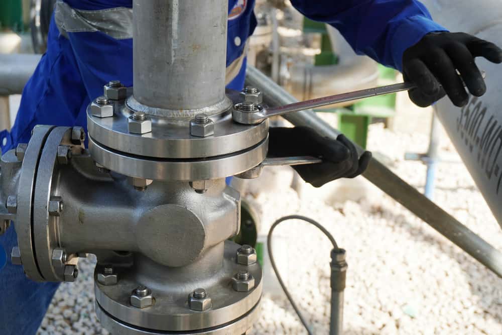
Example: 90-Degree Elbow Equivalent Length
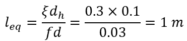
For example, a 100-mm flanged regular 90-degree elbow with a minor loss coefficient of 0.3 and connected to a steel pipe with a friction factor of 0.03 will have an equivalent length equal to 1 meter, as shown in the calculations below.
Equivalent Lengths Of Common Fittings
Using the formula above for each and every fitting can be tedious, especially since most piping networks use a lot of fittings. Hence, the estimated equivalent lengths of the most common fittings have already been tabulated below for easy reference.
Even though factors like pipe roughness and fluid properties are likely to be different from the conditions under which these data have been obtained, it was found that changes in these parameters result in minuscule variations in the Equivalent Length / Diameter ratio. It means that the le/dh ratio is virtually constant for a specific type of fitting, making it possible to have this kind of table.
It should be noted, however, that using these tabulated values in pressure loss calculations can result in up to a 30% error for turbulent flow and up to 50% error for laminar flow. These are fine in doing most preliminary calculations. However, using other methods like the 3K method is more appropriate to obtain accurate results.
The table below shows the equivalent lengths of common valves and fittings, expressed as a ratio of the length to the diameter, or le/dh. It is important to note that the tabulated values below are le/dh ratios. Some publications specify the actual equivalent lengths of pipe fittings instead of these ratios.