Piping systems can be classified into two types based on the driving force that enables fluid flow: pressure-driven and gravity pipe flow. Pressure-driven systems rely on external forces like pumps to create a pressure difference, whereas gravity pipe flows utilize the force of gravity to move the fluid using its own weight.

In this article, the focus is on the latter— exploring the concept of gravity pipe flow systems, their applications, and the calculations involved in their design.
Gravity Pipe Flow Explained
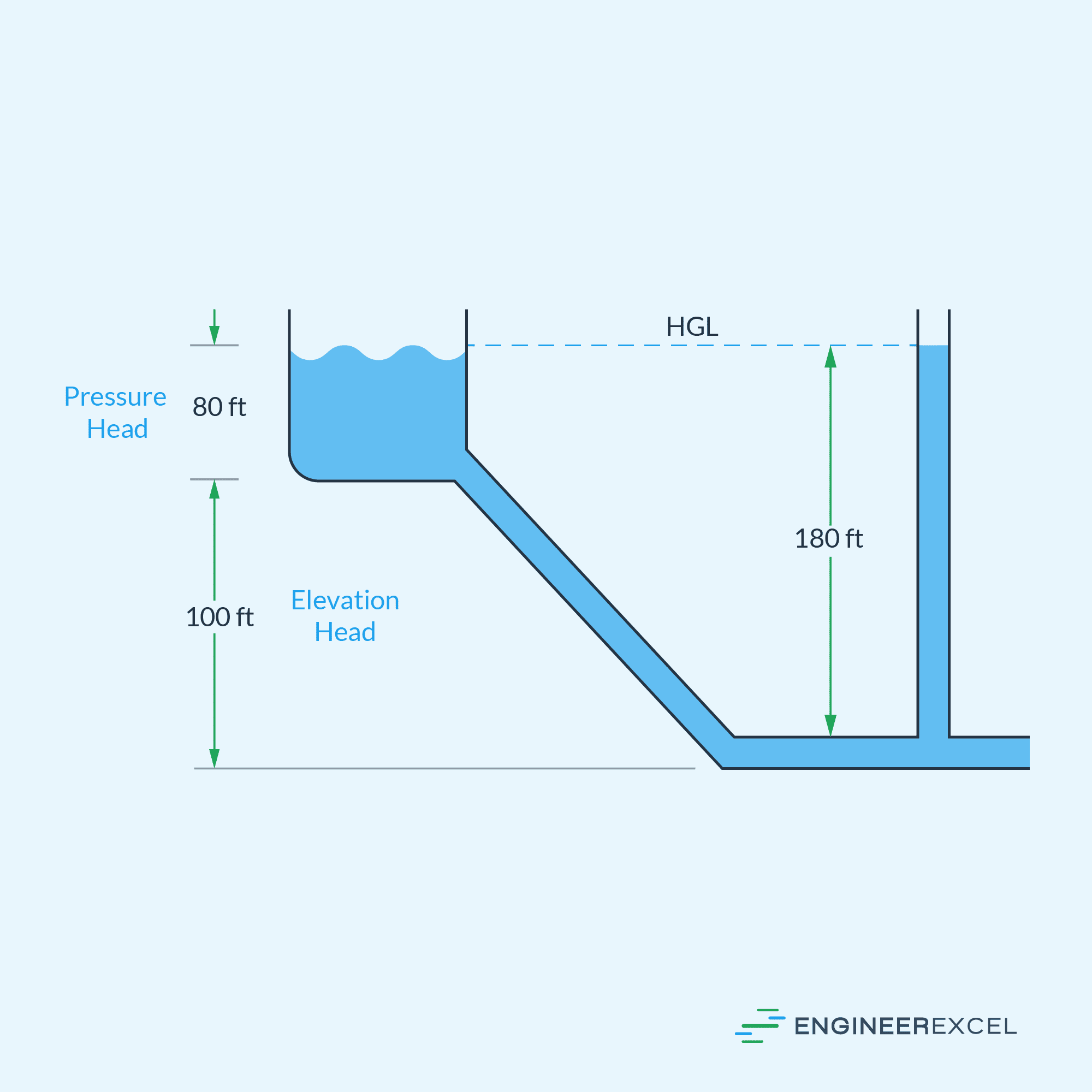
Gravity pipe flow refers to the movement of fluid through a pipe system solely under the influence of gravity. Unlike pressurized systems that require mechanical pumps or external energy sources to propel the fluid, gravity pipe flow relies on the natural downward flow of fluids due to the gravitational pull. To achieve this, the pipe is inclined up to a certain degree above the horizontal to create the necessary hydraulic head, as depicted in the diagram below.

Elevate Your Engineering With Excel
Advance in Excel with engineering-focused training that equips you with the skills to streamline projects and accelerate your career.
The hydraulic head represents the potential energy of the fluid due to its elevation above the discharge point. In a gravity pipe flow, it can be divided into two components: the elevation head and the pressure head.
The pressure head accounts for the pressure caused by the height of fluid in the source tank, while the elevation head accounts for the elevation of the tank above the discharge point, which is also equal to the vertical component of the pipeline. Hence, the higher the tank and height of fluid, the greater the potential energy available to drive the flow.
A gravity pipe flow is treated similar to an open channel flow, and can be analyzed using the same principles and equations of open channel hydraulics
Purpose And Applications Of Gravity Piping
Using gravity pipe flow is a cost-effective and energy-efficient way to transport fluids from one place to another. When considering energy options for designing pipe systems, gravity pipe flow is usually the first choice because it requires no additional external energy to move water. By using gravity, the need for pump or other fluid handling equipment is eliminated, allowing the system to minimize operational costs and reduce the risk of mechanical problems.
Gravity pipe flow is commonly used in systems where there is no need to maintain a specific pressure level. In water supply systems, for example, gravity piping is often used to distribute water from reservoirs or elevated sources to homes and buildings. Additionally, most sewage systems also rely on gravity to carry sewage and wastewater from buildings and industrial facilities to treatment plants and disposal sites.
In stormwater drainage systems, gravity is used to move rainwater and runoff away from roads and other surfaces through a network of drains, catch basins, and underground pipes. The water is eventually released into natural water bodies or detention basins to prevent flooding.
In some cases, gravity piping can also be used in industrial facilities to transfer substances like chemicals, oils, and slurries between tanks. By designing facilities to take advantage of gravity, where applicable, the operational and maintenance costs of the plant are reduced.
Water Flow Calculations In Gravity Pipe Flow
Water is the most commonly used fluid in gravity pipe flow applications. Hence, most calculations involved in the design of gravity-fed systems assume the properties of water.
In a typical gravity pipe flow, the fluid often does not completely fill the pipe’s cross-section during operation, as shown in the diagram below. Since there is a presence of free surface on the flow channel, gravity pipe flows are typically analyzed using the same principles as open channel hydraulics.
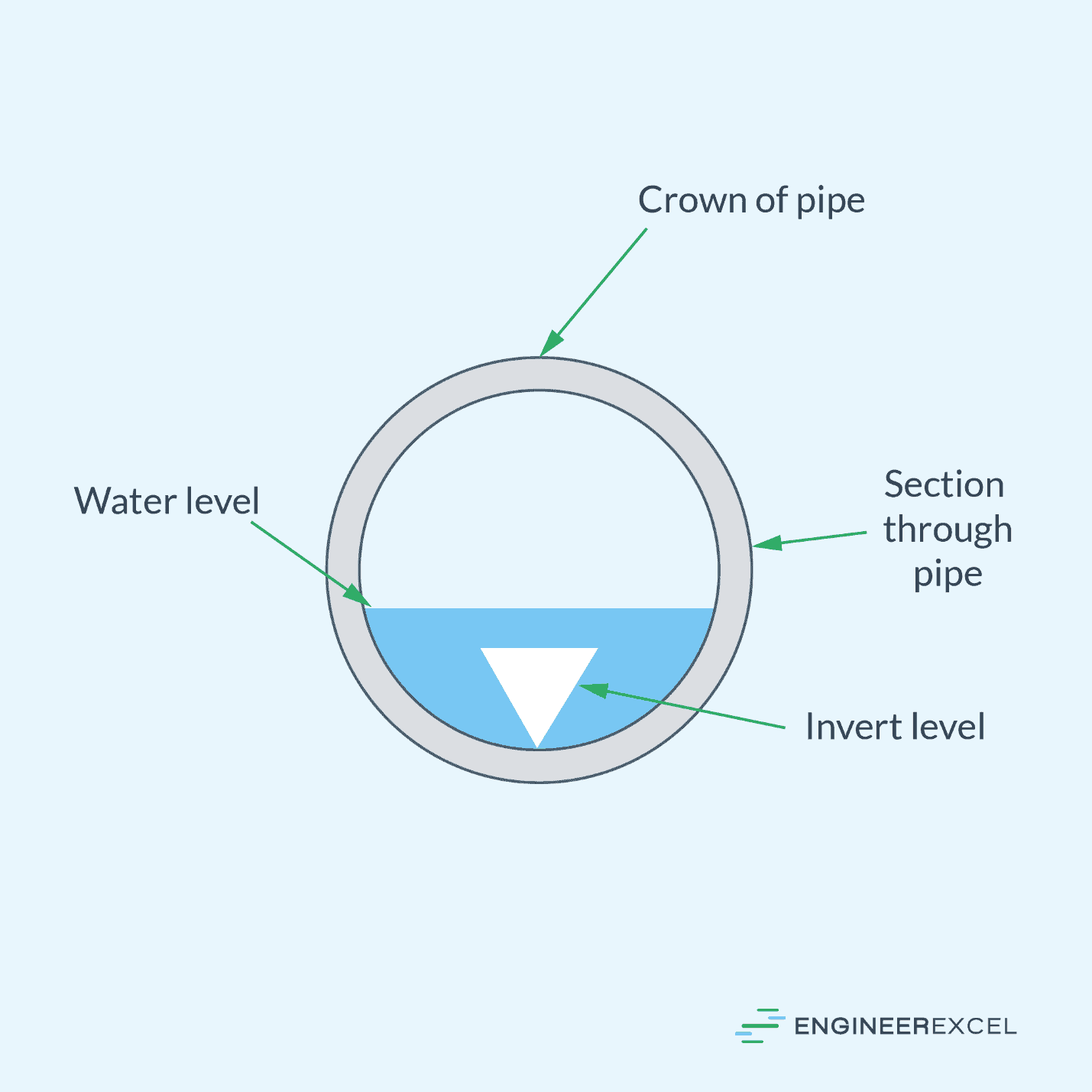
As shown in the diagram above, the pipe wall in a partially full pipe can be divided into two sections: the crown, which refers to the top of the inside pipe wall, and the invert, which refers to the bottom of the pipe wall. When designing gravity pipe flow systems, the primary objective is to determine the optimal slope of the invert as well as the appropriate pipe size and wetted perimeter to effectively handle the desired discharge capacity.
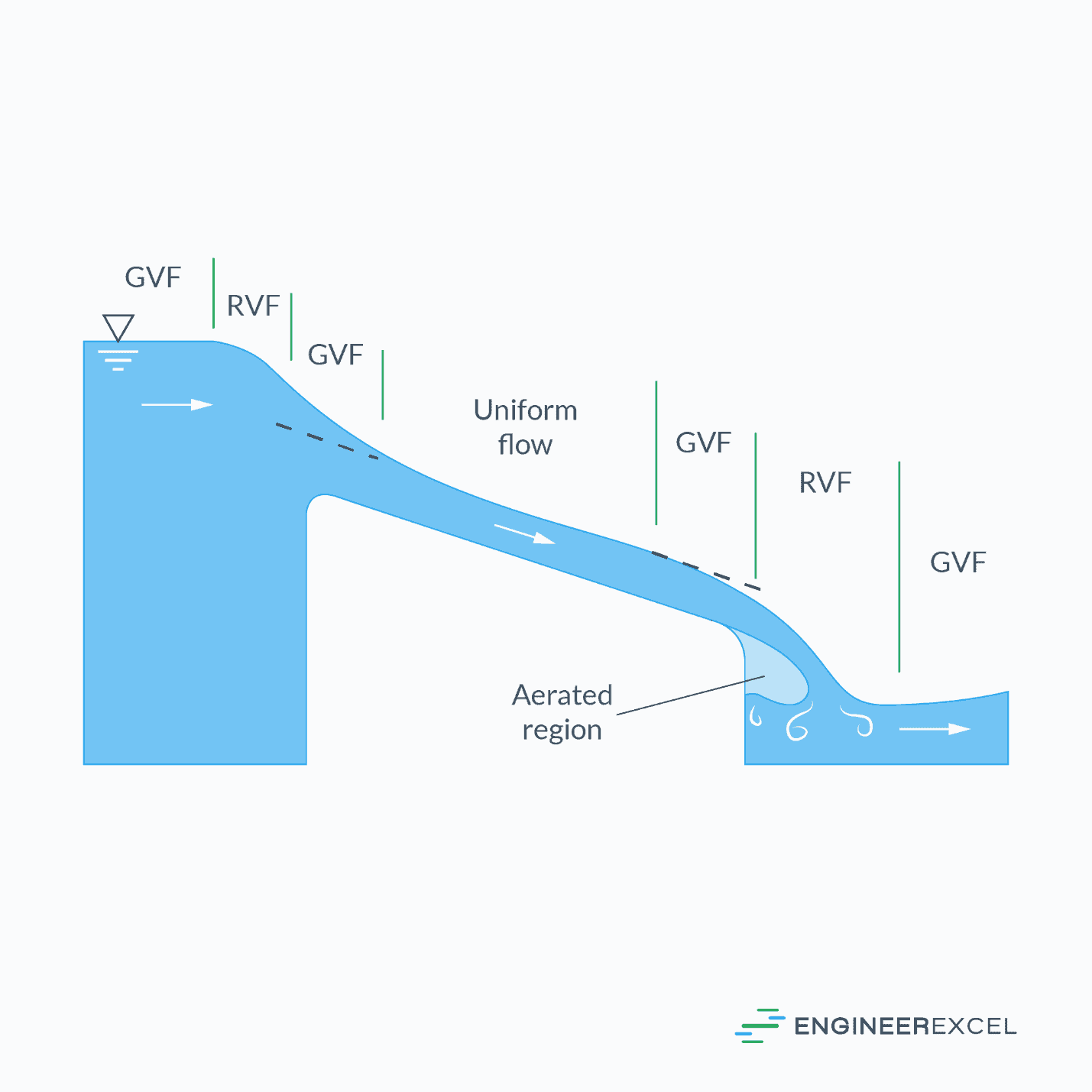
In open channel hydraulics, calculations typically assume steady uniform flow conditions. Steady flow refers to a constant discharge over time, while uniform flow implies that both the slope of the water surface and the cross-sectional flow area are constant. In steady, uniform-flow scenarios, the slope of the water surface corresponds to the slope of the channel bottom, as illustrated in the diagram below.
Flow Velocity In Gravity Pipe Flow
Flow velocity refers to the speed at which the fluid moves through the pipe. It is a critical parameter to consider when designing a gravity pipe system since it relates directly to the discharge capacity.
The flow velocity in gravity pipe flow can be calculated using the Manning’s equation, which relates the pipe slope, hydraulic radius, and Manning’s roughness coefficient. It has two forms: one in SI units and the other in English units.
The SI unit form of the Manning formula for calculating the uniform flow velocity is as follows:
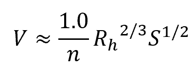
Where:
- V = flow velocity [m/s]
- Rh = hydraulic radius [m]
- S = slope of the pipe [unitless]
- n = Manning’s roughness coefficient [unitless]
On the other hand, the English unit form of the same formula is as follows:
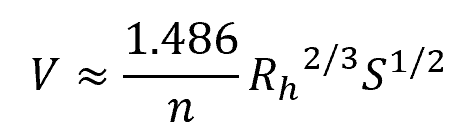
Where:
- V = flow velocity [ft/s]
- Rh = hydraulic radius [ft]
Note that the Manning formula is only an approximation and is not dimensionally consistent. According to the formula, increasing the pipe inclination and hydraulic radius results in higher flow velocity. Additionally, a smoother pipe surface enhances the flow velocity compared to a rough surface.
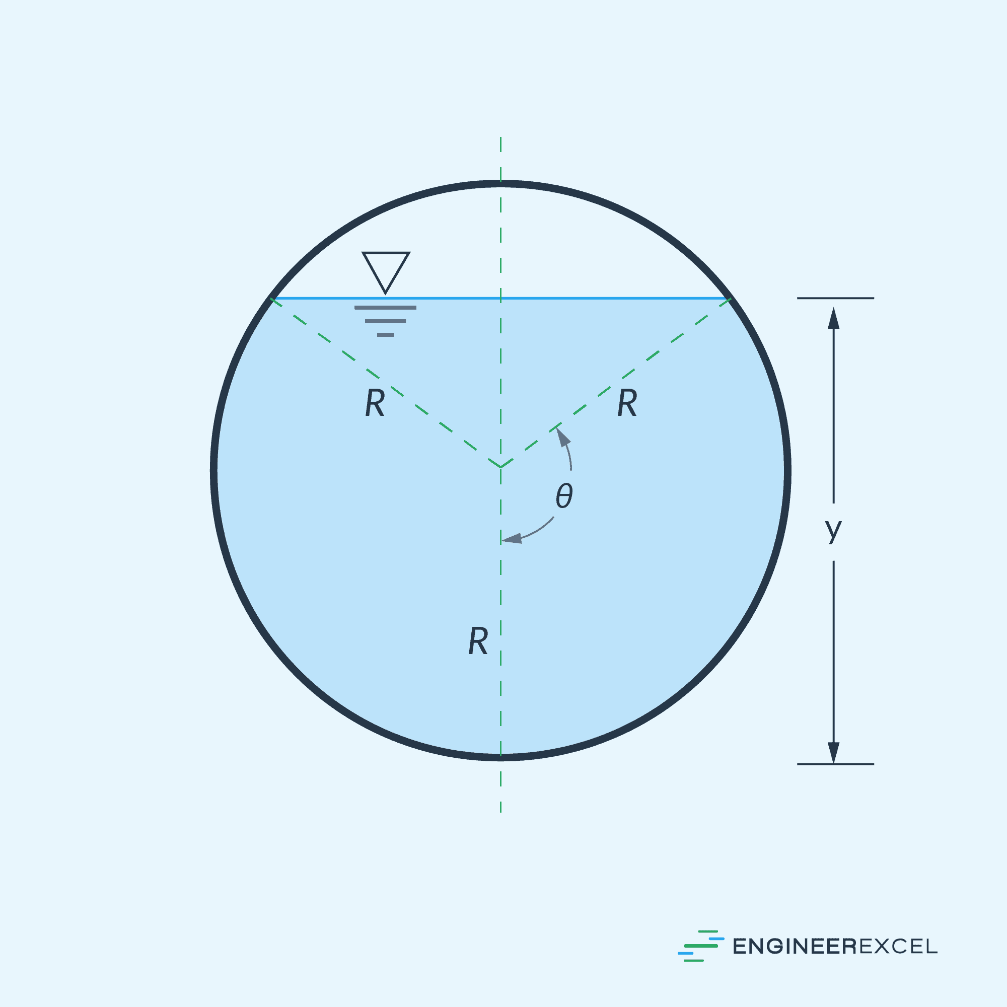
The hydraulic radius is the ratio of the cross-sectional area of the flow to the wetted perimeter. For a circular pipe, shown in the diagram above, the hydraulic radius can be calculated using the formula:
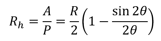
Where:
- A = cross-sectional area of the flow [m2 or ft2]
- P= wetted perimeter [m or ft]
- R = radius of the pipe [m or ft]
- θ = half of the invert angle [deg or rad]
The Manning’s roughness coefficient is a dimensionless value that represents the relative roughness of the surface of the conduit. Its value depends on the material and age of the pipe. It can range from 0.01 for smooth surfaces to 0.03 for very rough surfaces.
Flow Rate In Gravity Pipe Flow
Flow rate represents the volume of fluid passing through the pipe per unit of time. For a gravity pipe flow, it can be calculated by multiplying Manning’s formula for flow velocity with the flow area.
In SI units, the formula for volumetric flow rate becomes:
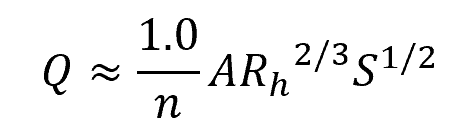
Where:
- Q = flow velocity [m3/s]
In English units, the formula becomes:
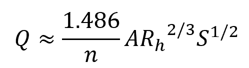
Where:
- Q = flow velocity [ft3/s]
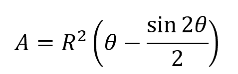
Note that for a partially full gravity pipe flow, the cross-sectional area of the flow can be calculated using the formula:
Required Slope For Gravity Pipe Flow
The slope of the pipe plays an important role in the design of gravity pipe flow as it directly influences the fluid’s flow rate. A steep slope allows for faster flow, while a gentle slope results in slower flow rates.
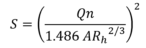
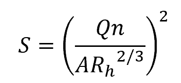
Given a desired flow rate, the equation above can be rearranged to obtain the required pipe slope. In SI units, the required slope can be calculated using the formula:
In English units, the same formula takes the following form: