
What is Friction Factor
The friction factor is a dimensionless quantity that represents the resistance to the flow of fluid in a conduit due to the effect of viscosity. It plays an important role in fluid mechanics calculations, particularly in determining the pressure drop or head loss in a fluid system.
There are two types of friction factors: the Darcy friction factor and the Fanning friction factor. The Darcy friction factor is commonly used in engineering applications and is represented by the symbol fD or simply f. The Fanning friction factor, represented by ff is one-fourth the value of the Darcy friction factor.
The main difference between them is the factor of four. Engineers can choose which friction factor to use, but they must remain consistent throughout the analysis.
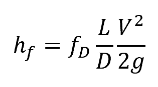
The most common equation used to calculate head loss using friction factor is the Darcy-Weisbach equation:

Elevate Your Engineering With Excel
Advance in Excel with engineering-focused training that equips you with the skills to streamline projects and accelerate your career.
Where:
- hf = head loss due to friction [Pa]
- fD = Darcy friction factor [unitless]
- L = length of pipe [m]
- D = hydraulic diameter of pipe [m]
- V = average fluid velocity [m/s]
- g = gravitational acceleration [9.81 m/s2]
Factors Affecting Friction Factor
Friction factor is primarily affected by two factors: Reynolds number and surface roughness of the conduit. Understanding these factors is important in minimizing pressure losses in a fluid flow system.
Reynolds Number
Reynolds number is a dimensionless quantity that describes the ratio of inertial forces to viscous forces in a fluid. It is defined as:
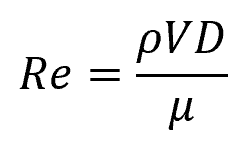
Where:
- Re = Reynolds number [unitless]
- ρ = density of the fluid [kg/m3]
- μ = dynamic viscosity of the fluid [Pa-s]
The relationship between the friction factor and Reynolds number varies with the flow regime. For laminar flow, the friction factor is inversely proportional with the Reynolds number, while for turbulent flow, it is a nonlinear function of the roughness of the pipe and the Reynolds number.
Conduit Shape
The shape of the conduit’s cross-section can also influence the friction factor. For example, a circular pipe typically has a lower friction factor compared to a non-circular conduit of the same cross-sectional area. This is because a circular shape allows for more uniform and efficient flow.
Surface Roughness of the Conduit
Particularly in turbulent flows, the roughness of the conduit wall affects the friction factor. Rougher surfaces create more turbulence, thus, increasing the friction factor. The roughness of the pipe is usually expressed in terms of the relative roughness, which is the ratio of the height of the roughness elements to the diameter of the pipe.
Determining Friction Factor Value
The friction factor can be calculated in experiments using the following formula:
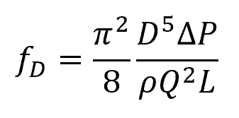
Where:
- ΔP = pressure drop [Pa]
- Q = volumetric flow rate [m3/s]
Alternatively, if it is impractical to determine the friction factor value experimentally, it can be calculated using established formulas, depending on flow regime.
Friction Factor Calculation in Laminar Flow
In laminar flow, which typically occurs at low Reynolds numbers, the flow is smooth and well-ordered. In this case, the value of the friction factor is solely dependent on the Reynolds number. Moreover, the formula for calculating the friction factor depends on the cross-sectional geometry of the conduit, as shown in the table below.

Friction Factor Calculation in Turbulent Flow
In turbulent flow, the friction factor is generally influenced by both the Reynolds number and surface roughness of the conduit walls. However, in the case of smooth-walled pipes, the turbulent friction factor can be estimated using an empirical formula that depends solely on the Reynolds number, as follows:
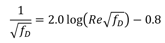
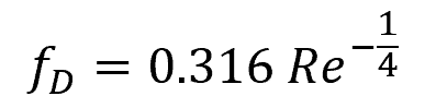
The above equation was developed by Prandtl. However, since it is implicitly structured, many alternative explicit approximations have been developed. One example is the Blasius equation below:
For rough-walled pipes, the friction factor tends to increase as the relative roughness (ε/D) increases. However, once the Reynolds number is high enough, the friction factor will eventually reach a stable value and remain constant for a given relative roughness.
This behavior is illustrated in the diagram below.

The graph above shows that, for a fully rough flow, the friction factor becomes independent of Reynolds number. In this region, the friction factor can be calculated using the following formula:
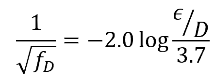
Where:
- ε = average height of irregularities on the conduit surface [mm or in]
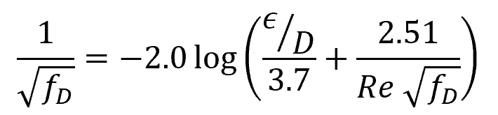
The equations for smooth-walled and fully-rough flows were interpolated by Colebrook to obtain the general formula for friction factor in turbulent flow, as follows:
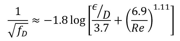
Since the above formula is implicit in nature, alternative explicit formulas have been developed. One example is the Haaland equation below:
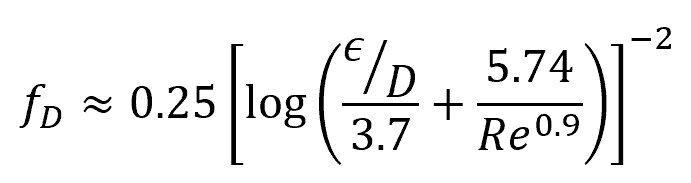
Another example is the Swamee-Jain approximation:
Moody Chart
Alternatively, the Darcy friction factor can be approximated using the Moody chart below. This chart illustrates the relationship between friction factor, Reynolds number, and relative roughness for a given flow regime, based on the Colebrook equation.

Example Problem
Problem: A pipe with a diameter of 0.1 meters and a length of 10 meters is used to transport water at a flow velocity of 0.1 meters per second. The pipe roughness is 0.0015 millimeters. Calculate the friction factor for this system. Note that the dynamic viscosity of water at room temperature is about 0.001 Pa-s.
Solution: To calculate the friction factor, we need to use the Colebrook equation, which relates the friction factor to the Reynolds number and the relative roughness of the pipe.
The Reynolds number can be calculated as:
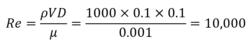
The relative roughness is ε/D = 0.0015 mm / 100 mm = 0.000015.
Using these values, we can solve for the friction factor using the Haaland equation:
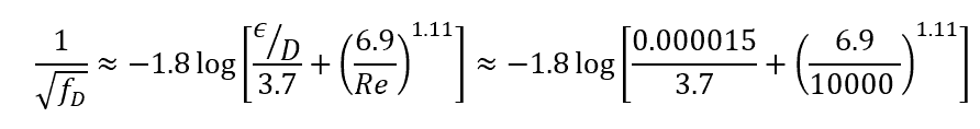
The Darcy friction factor for this system is approximately 0.025.