
When it comes to fluid flow in pipes, the diameter of the pipe plays a crucial role in determining the flow rate. In general, a larger diameter pipe allows for greater flow rates with less resistance, while a smaller diameter pipe will restrict flow and increase resistance.
Understanding this relationship between flow and pipe diameter is important in designing efficient pipe networks.
Understanding The Relationship Between Flow and Pipe Diameter
Flow refers to the movement of fluid through a pipe system. This flow rate is often measured in units like gallons per minute (GPM) or liters per second (L/s).
In general, the magnitude of the flow rate is affected by the pipe diameter.

Elevate Your Engineering With Excel
Advance in Excel with engineering-focused training that equips you with the skills to streamline projects and accelerate your career.
Following the conservation of mass principle, a larger diameter allows for a higher flow rate at a given fluid velocity. This is due to a larger cross-sectional area being available for the fluid to pass through. In contrast, a smaller diameter pipe would result in a lower flow rate for the same flow velocity.
In the same sense, if the flow rate is held constant, a bigger pipe diameter results in a lower fluid velocity, which contributes to less friction. Lower friction leads to less pressure loss along the pipe, making it more efficient for fluid transportation.
Because these parameters are interconnected, choosing the appropriate pipe diameter is crucial in maintaining optimal conditions. If flow is too high for a given pipe diameter, pressure drop increases, leading to potential pipeline damage or undesired operation. Conversely, when flow is too low for a given pipe diameter, fluid may stagnate, leading to potential contamination or low system efficiency.
By understanding the relationship between flow and pipe diameter, you can make appropriate choices based on the required flow rate and the desired system efficiency.
Calculating Flow from Pipe Diameter
The method for calculating flow rate from pipe diameter varies depending on whether the piping system is pressurized or gravity flow. In a pressurized piping system, the flow rate is determined by the pressure differential between the inlet and outlet of the pipe, while in a gravity flow piping system, the flow rate is determined by the slope of the pipe and the height of the fluid above the outlet.
Pressurized Pipe Flow
Pressurized pipe flow refers to the flow of a fluid through a closed pipe under pressure. In this type of flow, the fluid is forced through the pipe by a pump or other means of pressure, which creates a continuous flow of the fluid. Pressurized pipe flow is commonly used in various industries, such as oil and gas, chemical, and water treatment, to transport fluids from one point to another.
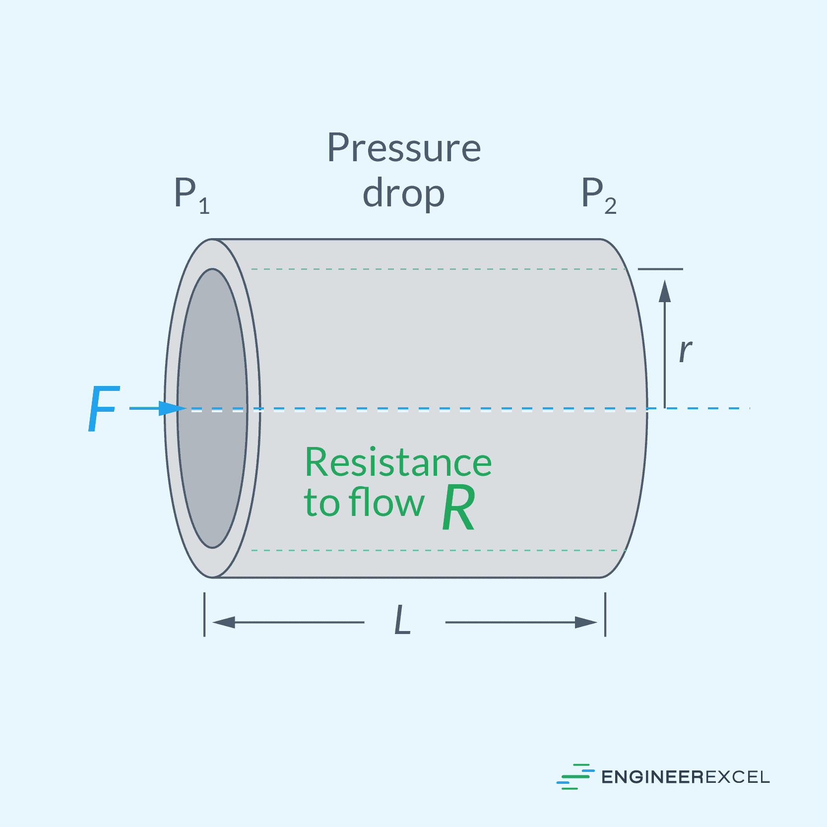
The formula for calculating flow rate from pipe diameter in pressurized flow depends the flow regime. For laminar flow, Poiseuille’s equation can be used:
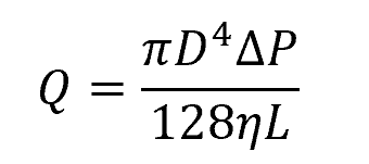
Where:
- Q = flow rate [m3/s]
- D = pipe diameter [m]
- ΔP = pressure drop [Pa]
- η = fluid viscosity [Pa-s]
- L = pipe length [m]
For turbulent flow, the flow rate can be calculated using the following empirical formula developed by Swamee and Jain:
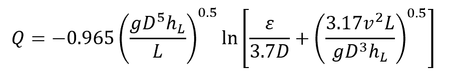
Where:
- hL = head loss across the pipeline [m]
- ε = pipe roughness [m]
- v = fluid velocity [m/s]
- g= gravitational acceleration [9.81 m/s2]
This formula is generally applicable for Reynolds numbers greater than 2000 and is accurate to within 2 percent of the Moody chart data. Alternatively, the Darcy-Weisbach equation can be used to iteratively calculate for fluid velocity and then multiply the fluid velocity by the pipe’s cross-sectional area to obtain flow rate.
Gravity Pipe Flow
Gravity pipe flow refers to the movement of fluid through a pipe due to the force of gravity. In this type of flow, the fluid moves from a higher elevation to a lower elevation, with the force of gravity providing the energy to move the fluid through the pipe. It is commonly used in water supply and drainage systems, as well as in the transportation of oils and other fluids.
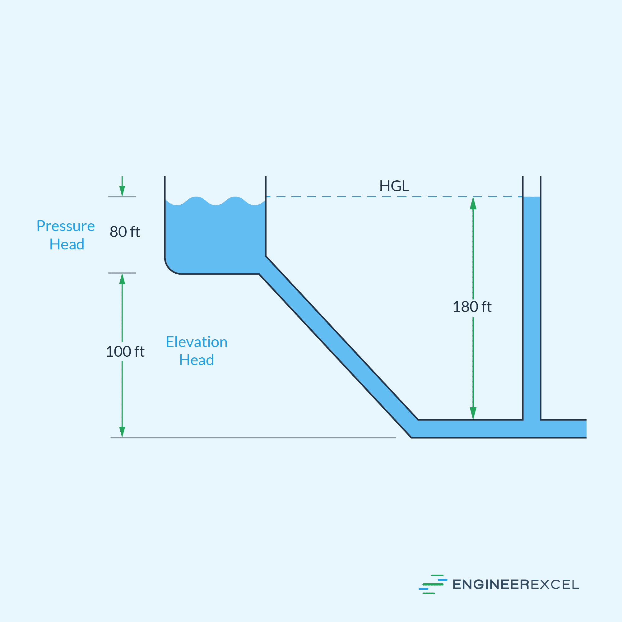
The flow rate and pressure of a gravity pipe system depend on several factors, including the elevation difference between the inlet and outlet of the pipe, the pipe’s diameter and length, and the properties of the fluid being transported. It’s worth noting that in this type of flow, the fluid may not completely fill the pipe’s cross-section during operation, as shown in the diagram below. Due to the presence of a free surface on the flow channel, the analysis of gravity pipe flows typically utilizes the same principles as open channel hydraulics.
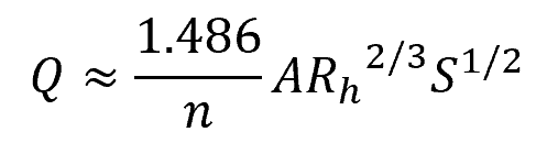
The flow rate in a gravity pipe flow can be calculated using the Manning’s formula, which can be written in SI units as follows:
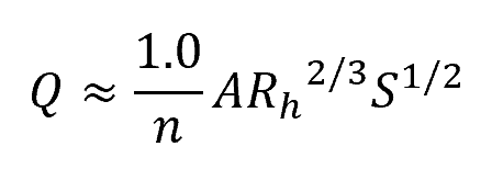
Where:
- Q = flow rate [m3/s]
- A = cross-sectional area of the flow [m2]
- Rh = hydraulic radius [m]
- S = slope of the pipe [unitless]
- n = Manning’s roughness coefficient [unitless]
Note that instead of the pipe diameter, the flow rate is more directly related to the hydraulic radius, which is the ratio of the cross-sectional area of the flow to the wetted perimeter. In English units, the formula becomes:
Where:
- Q = flow rate [ft3/s]
- A = cross-sectional area of the flow [ft2]
- Rh = hydraulic radius [ft]
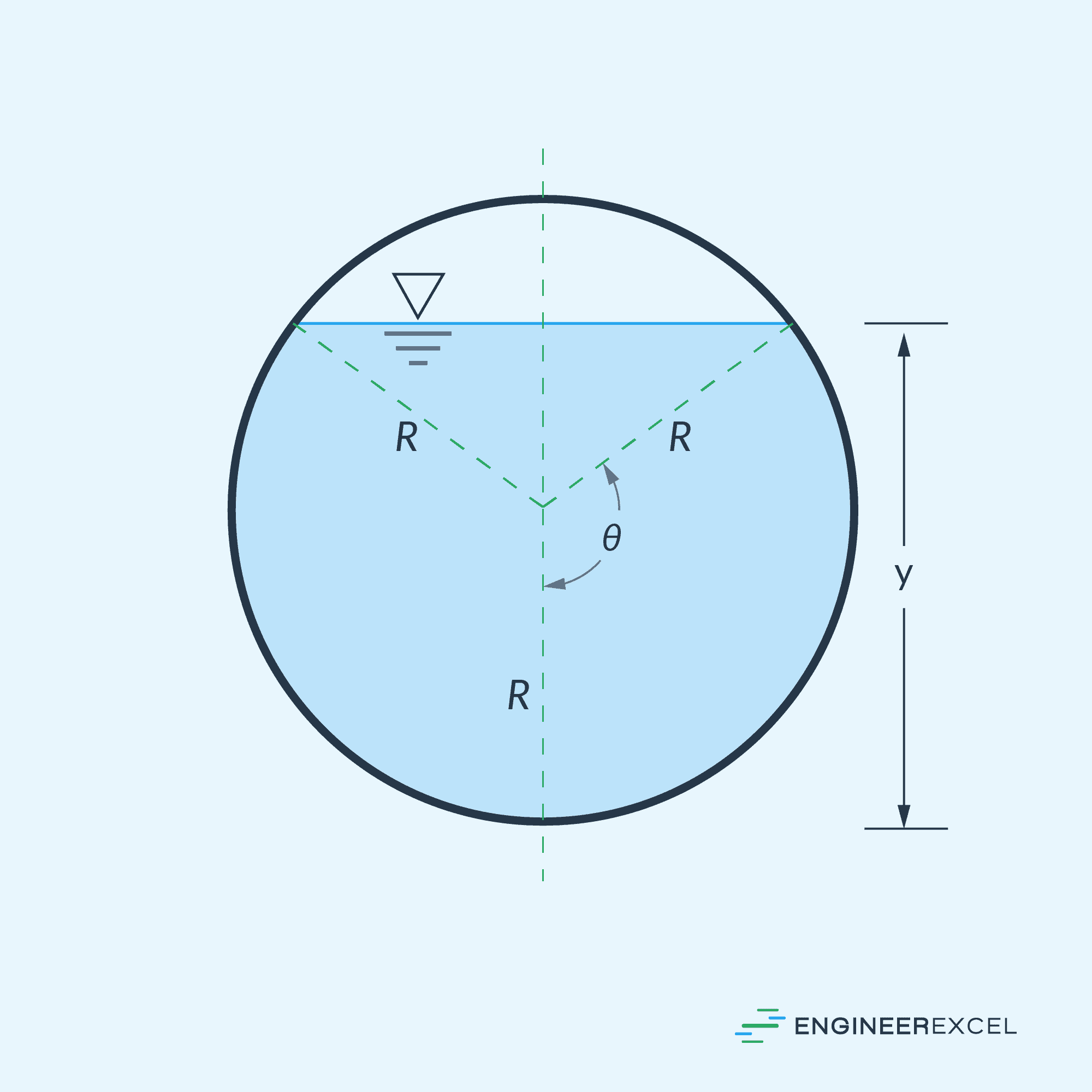
For a partially full gravity pipe flow, the cross-sectional area of the flow can be calculated using the formula:
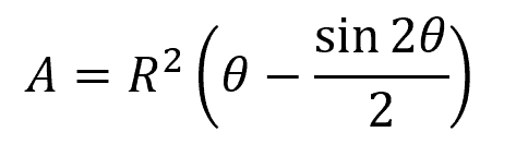
Where:
- R = radius of the pipe or half the diameter [m or ft]
- θ = half of the invert angle [deg or rad]