
Curious about the differences between Pitot tubes and Venturi meters? These devices are used to measure fluid flow rates in pipes or channels, but their designs, operating principles, and specific applications are notably different.
This article explores the operating principles of each device, their applications and limitations, and how engineers and researchers address potential issues to ensure accurate fluid velocity measurements.
Pitot Tube vs Venturi Meter
Pitot tube and Venturi meter are devices used to measure fluid flow rates in pipes or channels. Although both devices rely on the principle of differential pressure to determine how fast the fluid is moving, there are notable differences in their designs, operating principles, and specific applications.
Pitot Tube Operating Principle

Elevate Your Engineering With Excel
Advance in Excel with engineering-focused training that equips you with the skills to streamline projects and accelerate your career.
The Pitot tube, named after French engineer Henri Pitot, is composed of a slender tube with small holes drilled around its exterior and a center hole running along its axis. The center hole in the tube is kept separate from the outside holes, as shown in the diagram below.
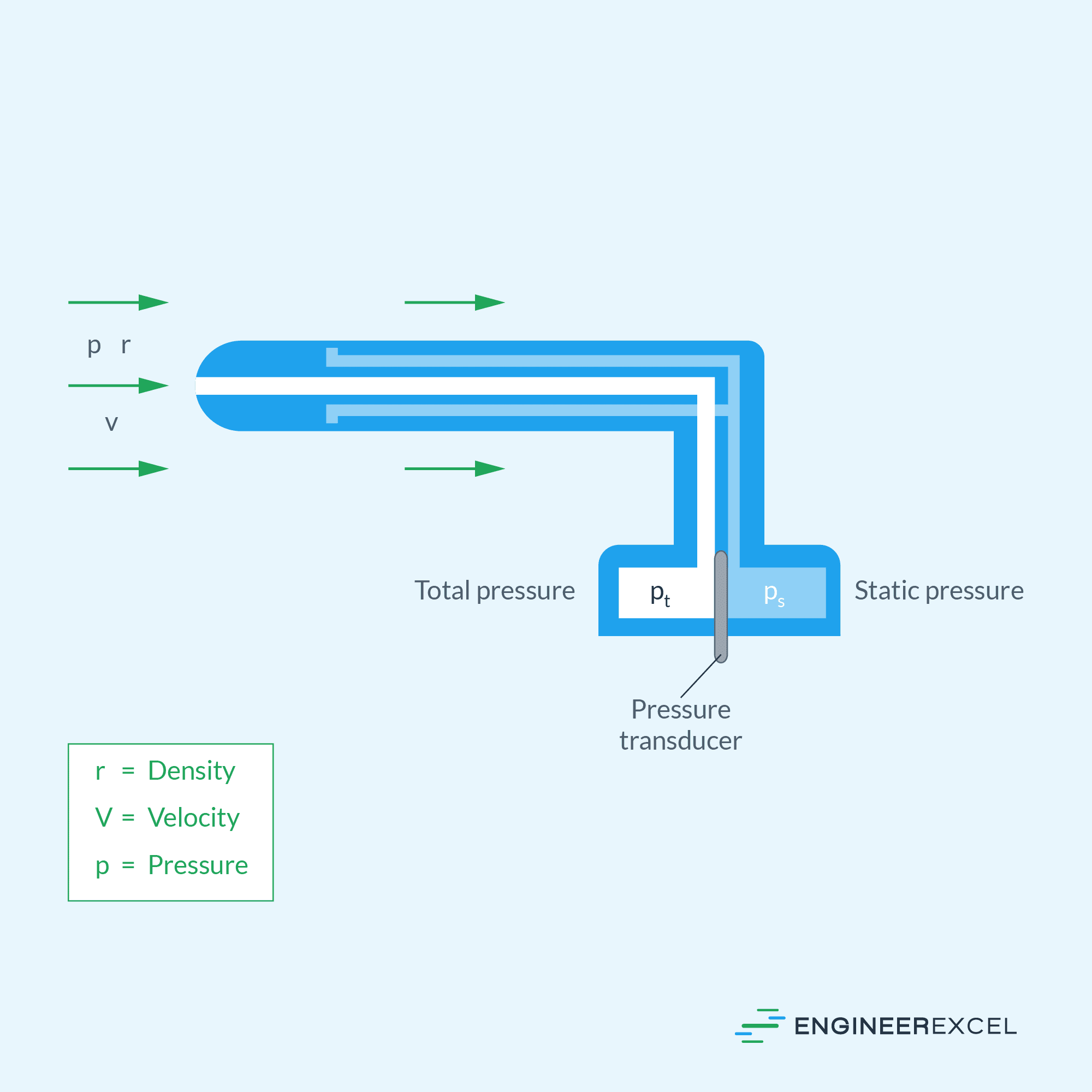
The center hole is positioned to always face the direction of the fluid flow being measured, while the openings of the outer holes are perpendicular to the fluid flow. Both ends of the tubes are connected to a device called a pressure transducer, which measures the difference in pressure between the two sections. It typically does this by measuring the strain in a thin element using an electronic strain gauge.
Since the outside holes are oriented perpendicular to the fluid flow, the tubes connected to them are pressurized only by the local random component of the air velocity. This means that the pressure in these tubes is equal to the static pressure of the fluid.
On the other hand, the center tube, which is oriented in the direction of travel, is pressurized both by the random and the ordered air velocity. This means that the pressure in the center tube is equal to the total pressure, which includes both the static pressure and the dynamic pressure caused by the fluid’s velocity.
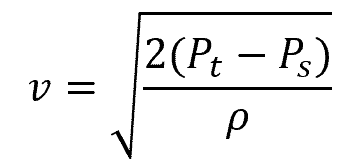
By measuring the difference in pressure between these tubes and using Bernoulli’s principle, the value of the dynamic pressure can be obtained. Consequently, the velocity of the fluid can be derived using the formula:
Where:
- v = fluid velocity [m/s]
- Pt = total pressure experienced at the center tube [Pa]
- Ps = static pressure [Pa]
- ρ = density of the fluid [kg/m3]
It is important to note that the pressure transducer used with Pitot tubes measures the pressure difference between the total and static pressures, rather than their absolute values.
Venturi Meter Operating Principle
The Venturi meter, named after Italian physicist Giovanni Venturi, consists of a converging section, a throat, and a diverging section. A simple diagram of a Venturi meter is shown below.
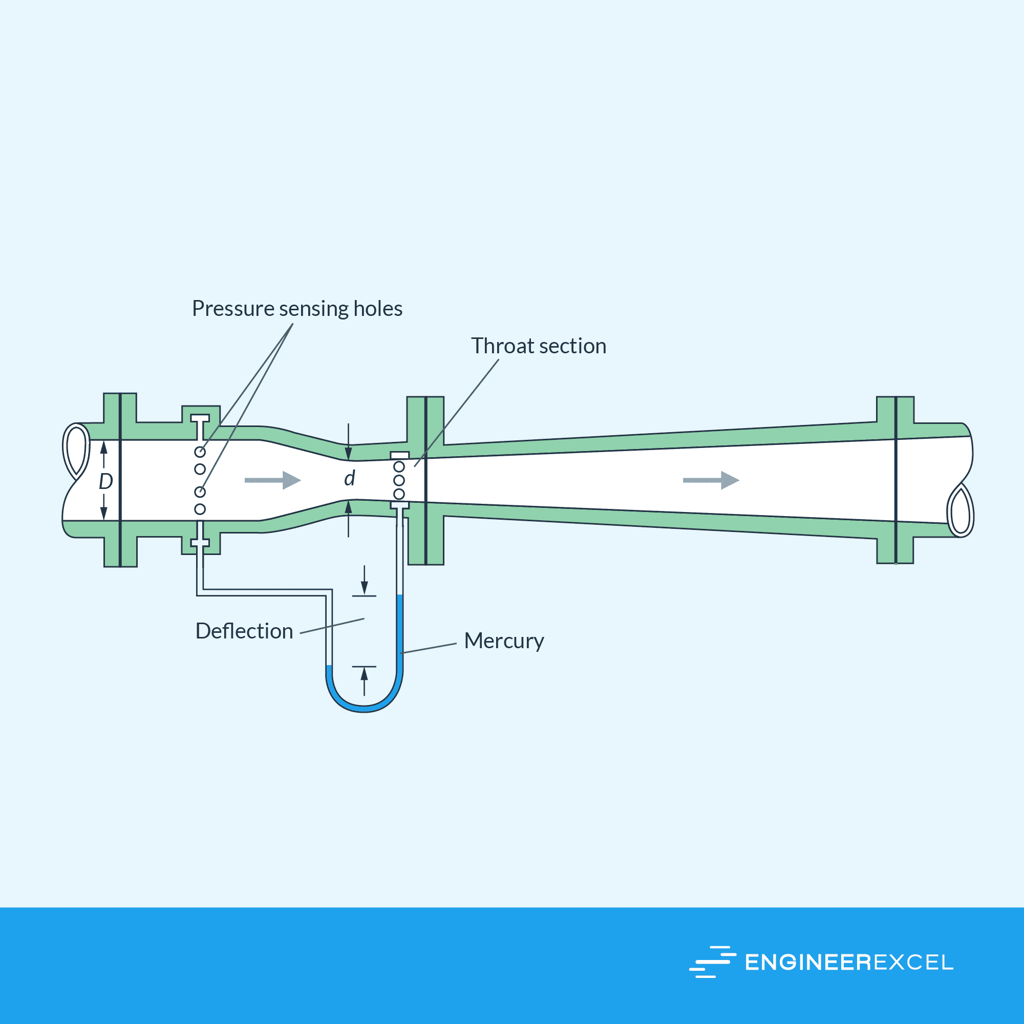
Similar to Pitot tubes, Venturi meters also rely on Bernoulli’s principle and the concept of differential pressures to measure fluid flow. When the fluid passes through the narrowest section of the tube, known as the throat, its velocity increases while the pressure decreases. This occurs because a portion of the static head is converted into velocity head.
Hence, a pressure difference develops between the throat and the surrounding channel. The magnitude of this pressure difference can then be directly related to the flow rate of the fluid being measured using the formula:
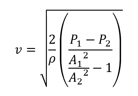
Where:
- P1 = static pressure at the main channel [Pa]
- P2 = static pressure at the throat [Pa]
- A1 = cross-sectional area of the main channel [m2]
- A2 = cross-sectional area of the throat [m2]
Note that this formula assumes an incompressible fluid that follows the continuity theory. That is, the volume of liquid that enters the pipe at one end will exit the other end at an equal volume rate.
Pitot Tube Applications and Limitations
Pitot tubes are used in a wide range of applications for flow measurement, including measuring air speed in racing cars, aircraft, as well as in industrial settings such as pipes, ducts, and stacks.
There are different types of pitot tubes. However, in general, they are used for medium to high fluid velocities, typically above 10 meters per second. They are not well-suited for very low-velocity applications because the transducer used in the tube may struggle to accurately measure the pressure difference at such velocities.
One of the major advantages of Pitot tubes is their simplicity. They have a straightforward design and can be easily installed in pipelines or ducts. Furthermore, Pitot tubes do not introduce significant pressure losses, making them ideal for applications where minimal interference is desired.
Pitot tubes offer an inexpensive alternative to orifice plates, with accuracy ranging from 0.5% to 5% and a flow rangeability of about 3:1.
Although Pitot tubes are generally used in high-speed flows, an issue arises when the fluid velocity exceeds the speed of sound, resulting in supersonic speeds. Under these conditions, the assumptions of Bernoulli’s equation do not hold, leading to incorrect measurements. This is because a shock wave occurs at the front of the tube, affecting the total pressure value.
Nonetheless, corrections such as the Prandtl-Glauert correction and the Crocco-Busemann correction can be applied to enable the use of Pitot tubes in high-speed aircraft. These corrections account for the compressibility effects and adjust the measured values for more accurate readings.
Furthermore, the local random component of air velocity can introduce pressure variations in Pitot tube readings, which can impact the accuracy and consistency of velocity measurements. To address this issue, engineers and researchers employ techniques such as filtering, signal processing, or utilizing Pitot tube designs that are less sensitive to turbulence. These measures help minimize the influence of local random velocity components and improve the reliability of fluid velocity measurements.
Venturi Meter Applications and Limitations
Venturi meters are widely used in various industries, including chemical plants, oil refineries, and HVAC systems, to monitor and regulate the flow rates of liquids. They are also essential in water and wastewater treatment facilities.
A venturi tube consists of a smaller diameter throat that fits into the pipeline. The restriction diameter should be within the range of 0.224 D to 0.742 D, where D represents the nominal bore diameter of the pipe. These tubes are normally available in sizes up to 72 inches.
Venturi flow meters are best suited for turbulent flow. Compared to Pitot tubes, they are better suited for lower-velocity flows, typically below 10 meters per second, where accurate measurement of the pressure differential across the device is possible.
Their rangeability varies from 4 to 1, and their accuracy is typically around 1% at the full range. They can be used with nearly all liquids, including those with high solid content, and are suitable for a wide viscosity range, from clean to dirty and viscous liquids.
The conical diffuser section downstream from the throat allows for excellent pressure recovery, resulting in low overall head loss. Venturi meters can handle large flow volumes with minimal pressure drops and can be mounted in large diameter pipes using flanged, welded, or threaded-end fittings.
Another advantage of venturi meters is their self-cleaning capability, thanks to their smooth internal contours. Their contoured design, combined with the self-scouring action of the flow through the tube, makes them resistant to corrosion, erosion, and internal scale build-up.
However, venturi meters are typically made from castings and require machining to meet close tolerances and replicate the standard design’s performance. As a result, they are heavy, bulky, and expensive. Because of their high cost, venturi tubes are primarily used in larger flows and more complex or challenging flow applications.
Accurate measurements also require careful installation and maintenance, including proper alignment and positioning to prevent flow disturbances and maintain desired accuracy.