
Calculating the deflection of a beam applies to several structural engineering scenarios. For example, calculating the deflection of a cantilever beam can determine the forces on an aircraft wing.
Beam Deflection Calculators
The easiest method for determining the deflection of a beam subject to a force or moment is to use a calculator and the parameters of the beam system. Depending on the beam system, cantilever, simply supported, or fixed-fixed, different cases have been evaluated to provide an equation for calculating the beam deflection as a function of the distance along the beam.
Cantilever Beam Deflection Calculators
There are five common cases for the consideration of cantilever beam deflection.
Cantilever Beam with End Force

Elevate Your Engineering With Excel
Advance in Excel with engineering-focused training that equips you with the skills to streamline projects and accelerate your career.
The first is the deflection due to a force at the free end of the beam, as shown below:
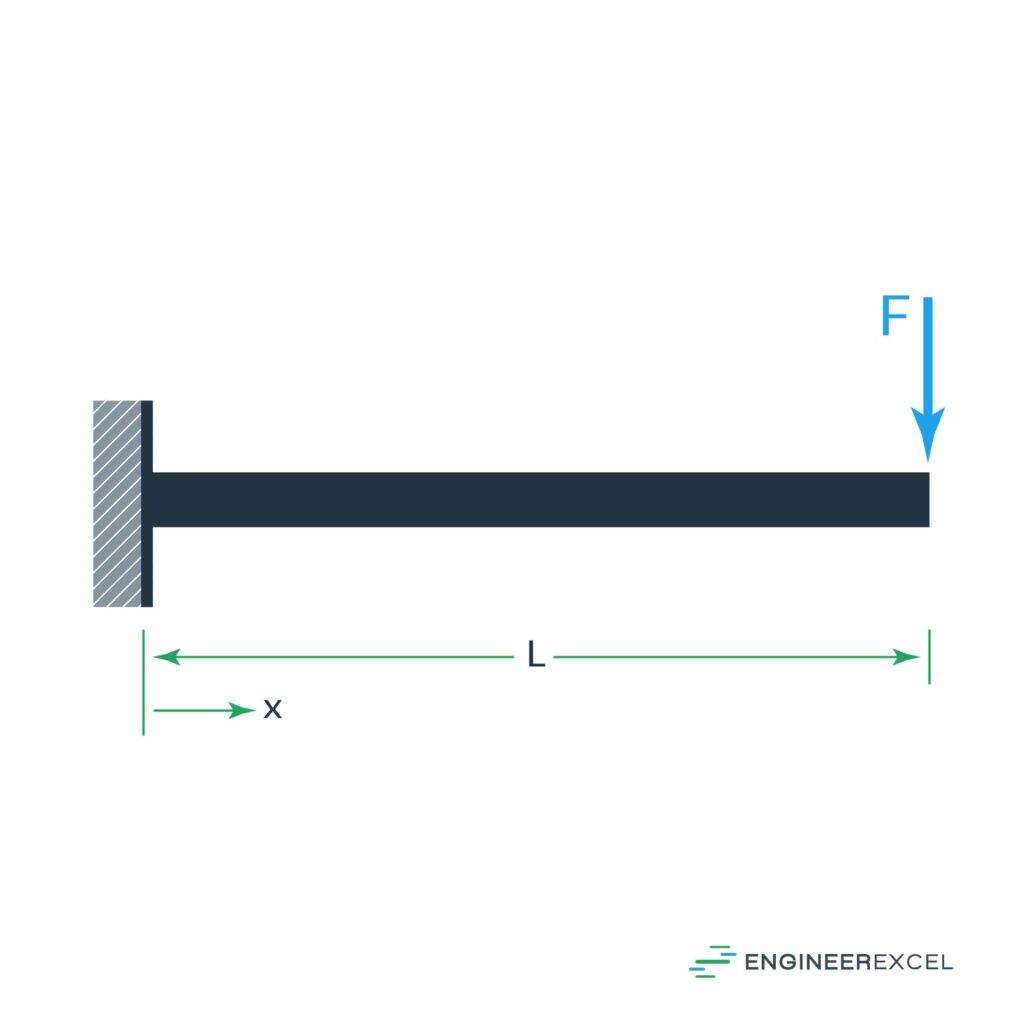
The deflection of the beam can be calculated using the following equation:

where:
- F is the force applied at the end of the beam (N)
- x is the position along the beam where the deflection is being evaluated (m)
- E is the Young’s modulus of the beam material (Pa)
- I is the area moment of inertia (m4)
- L is the total length of the beam (m)
Cantilever Beam with Load at Any Point
The second cantilever beam deflection is the deflection due to a force applied at some point other than the end, as shown below:
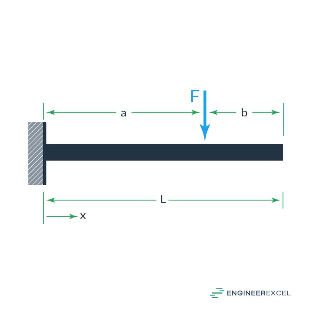
The deflection of the beam can be calculated using the following equations:


where a is the distance from the supported end to the location of the force (m).
Cantilever Beam With Uniform Distributed Load
The third cantilever beam deflection is the deflection due to a uniformly applied force along the length of the beam, as shown below:
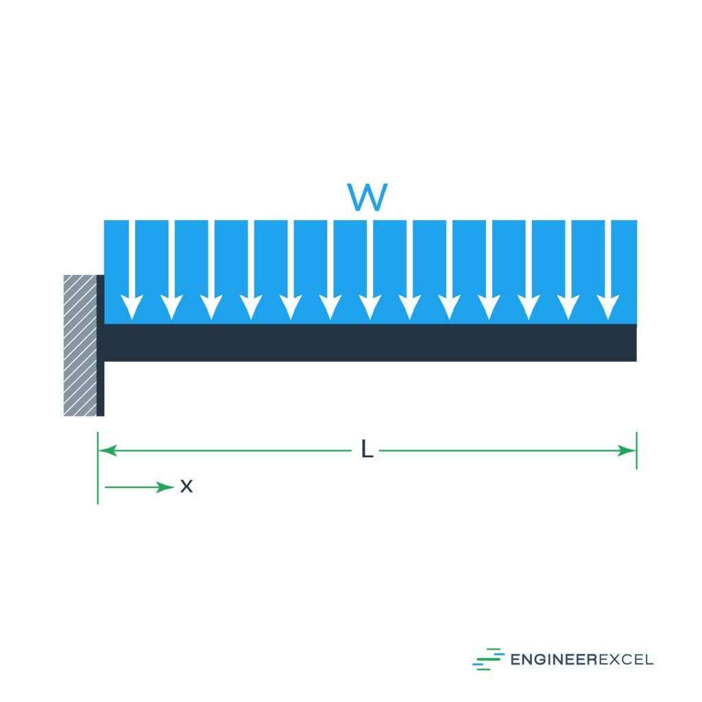
The deflection of the beam can be calculated using the following equation:

where w is the uniform load (N/m).
Cantilever Beam With Triangular Distributed Load
The fourth cantilever beam deflection is the deflection due to a triangular distributed force applied along the length of the beam, as shown below:
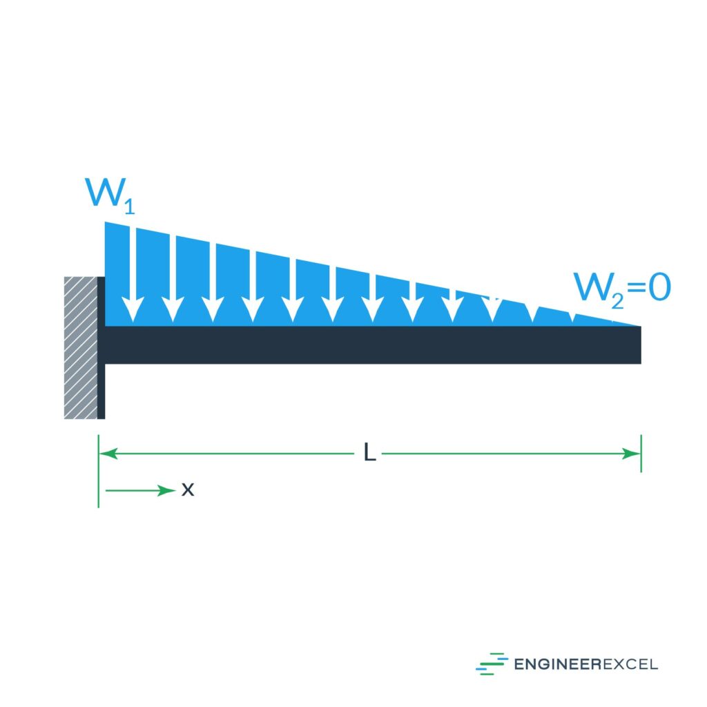
The deflection of the beam can be calculated using the following equation:

where w1 is the maximum value of the force (N).
Cantilever Beam with End Moment
The final cantilever beam deflection is the deflection due to a moment at the free end of the beam, as shown below:
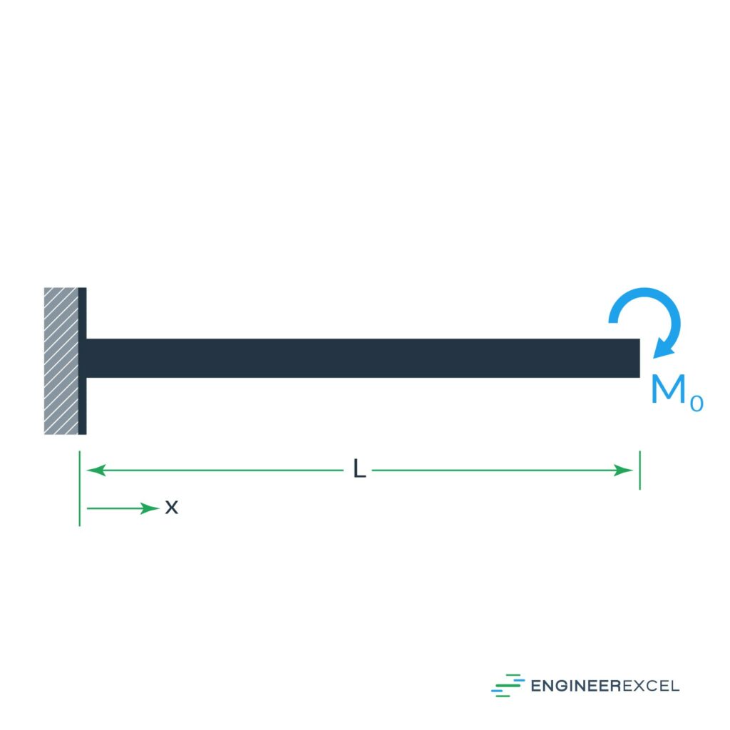
The deflection of the beam can be calculated using the following equation:

where M0 is the moment applied at the free end (N∙m).
Simply Supported Beam Deflection Calculators
Simply Supported Beam with Load at Any Point
There are seven common cases for the consideration of simply supported beam deflection. The first is the deflection due to an intermediate force, as shown below:
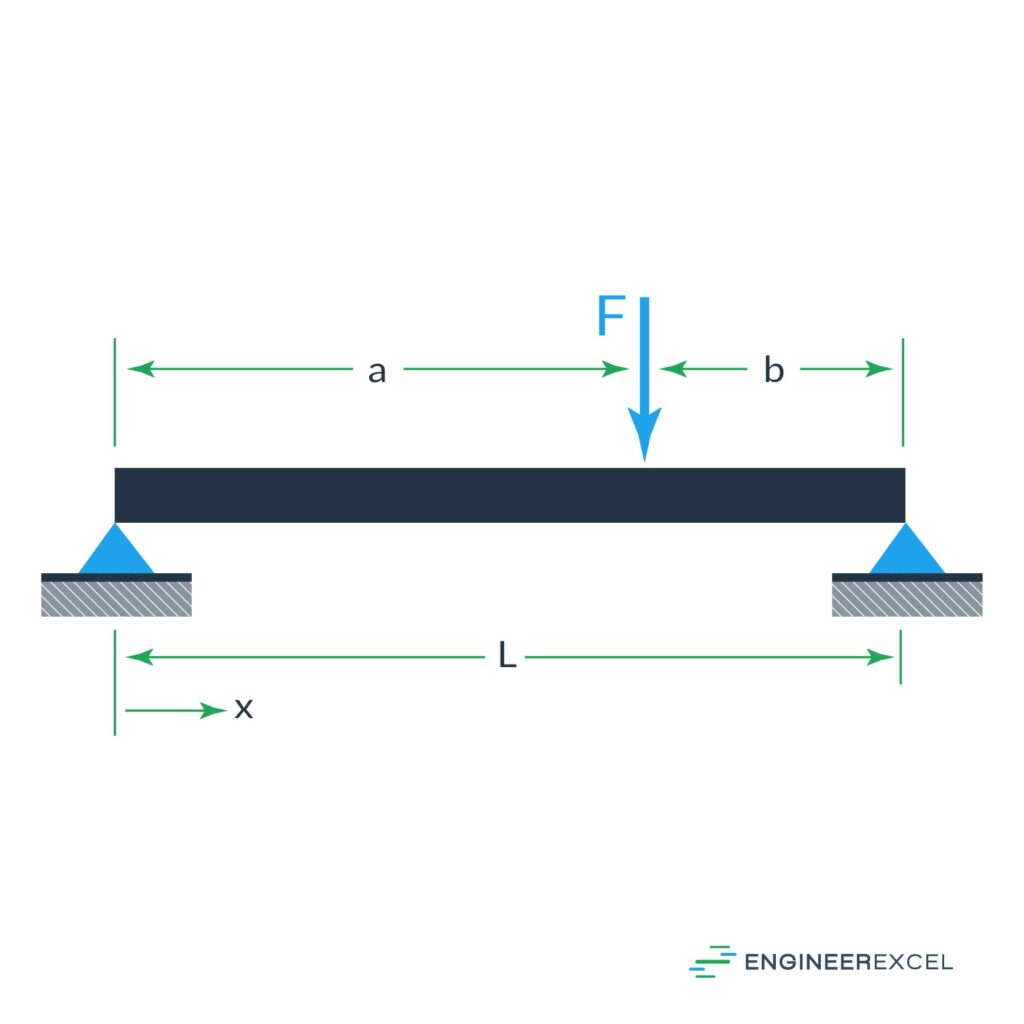
The deflection of the beam can be calculated using the following equation:

where a and b are the distances on either side of the applied force (m).
Simply Supported Beam with Load at Mid-Span
The second simply supported beam deflection is the deflection due to a force applied at the center of the beam, as shown below:
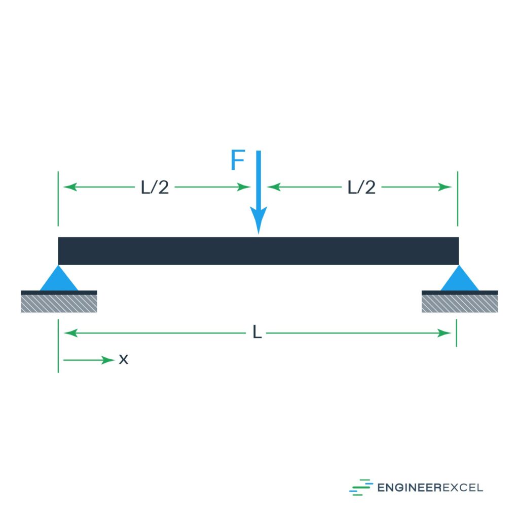
The deflection of the beam can be calculated using the following equation:

Simply Supported Beam with Uniform Distributed Load
The third simply supported beam deflection is the deflection due to a uniformly distributed force, as shown below:
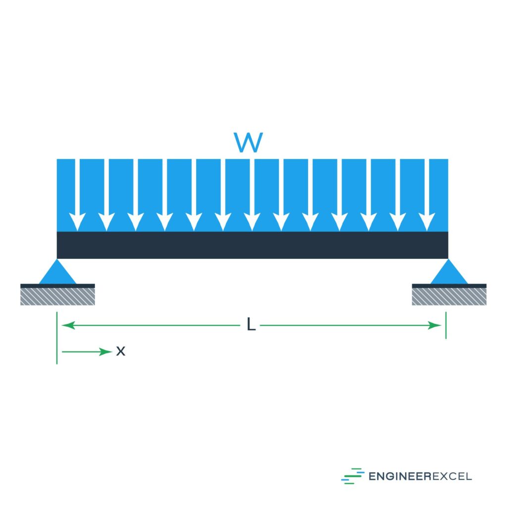
The deflection of the beam can be calculated using the following equation:

Simply Supported Beam with Moment at Each End
The fourth simply supported beam deflection is the deflection due to moments at both supports, as shown below:

The deflection can be calculated using the following equation:

Simply Supported Beam with Moment at One End
The fifth simply supported beam deflection is the deflection due to a moment at one support, as shown below:
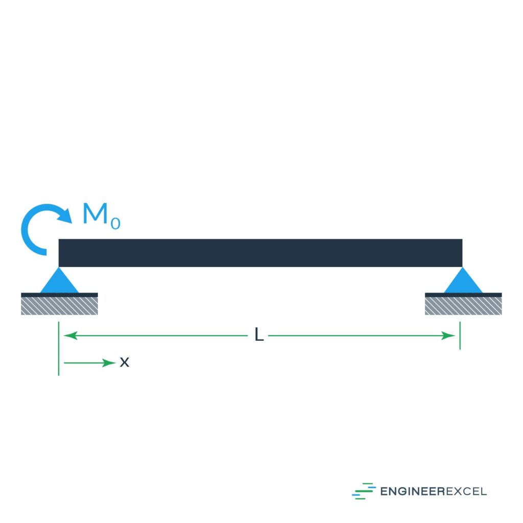
The deflection of the beam can be calculated using the following equation:

Simply Supported Beam with Moment at The Center
The final simply supported beam deflection is the deflection due to a moment at the center of the beam, as shown below:
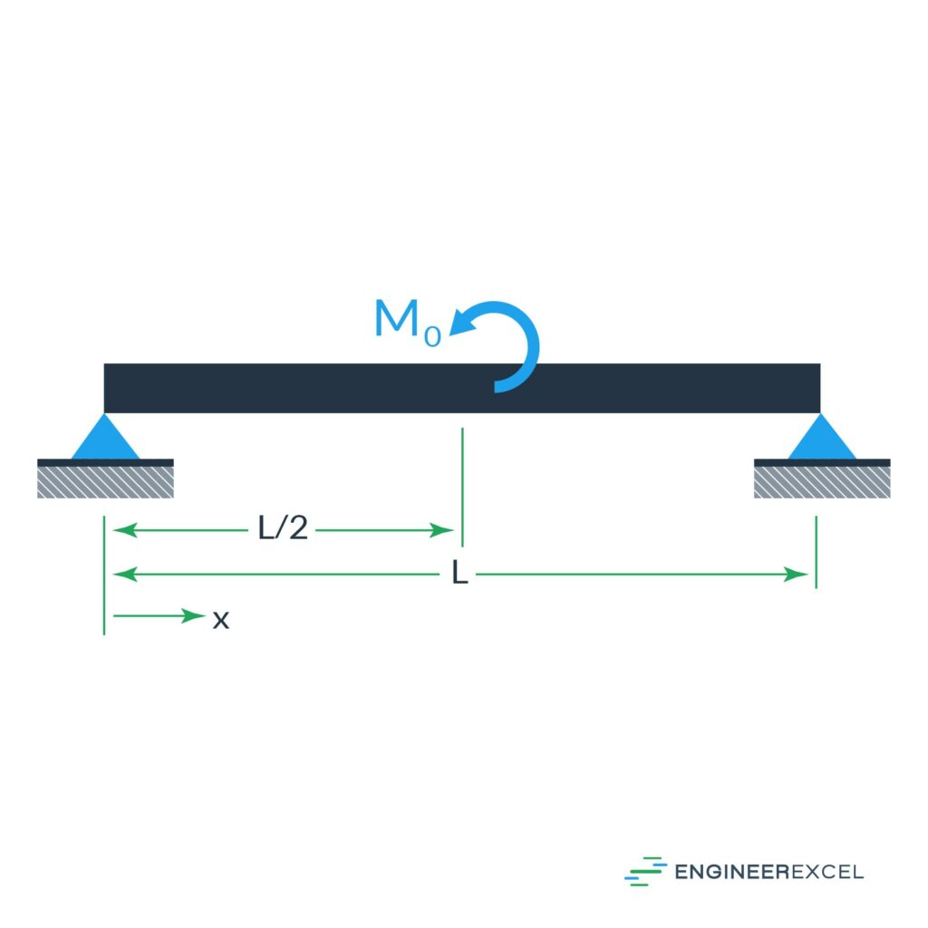
The deflection of the beam can be calculated using the following equation:

Fixed-Fixed Beam Deflection Calculators
Fixed-Fixed Beam with Load at Mid-Span
There are two common cases for the consideration of fixed-fixed beam deflection. The first is the deflection due to a force at the center, as shown below:
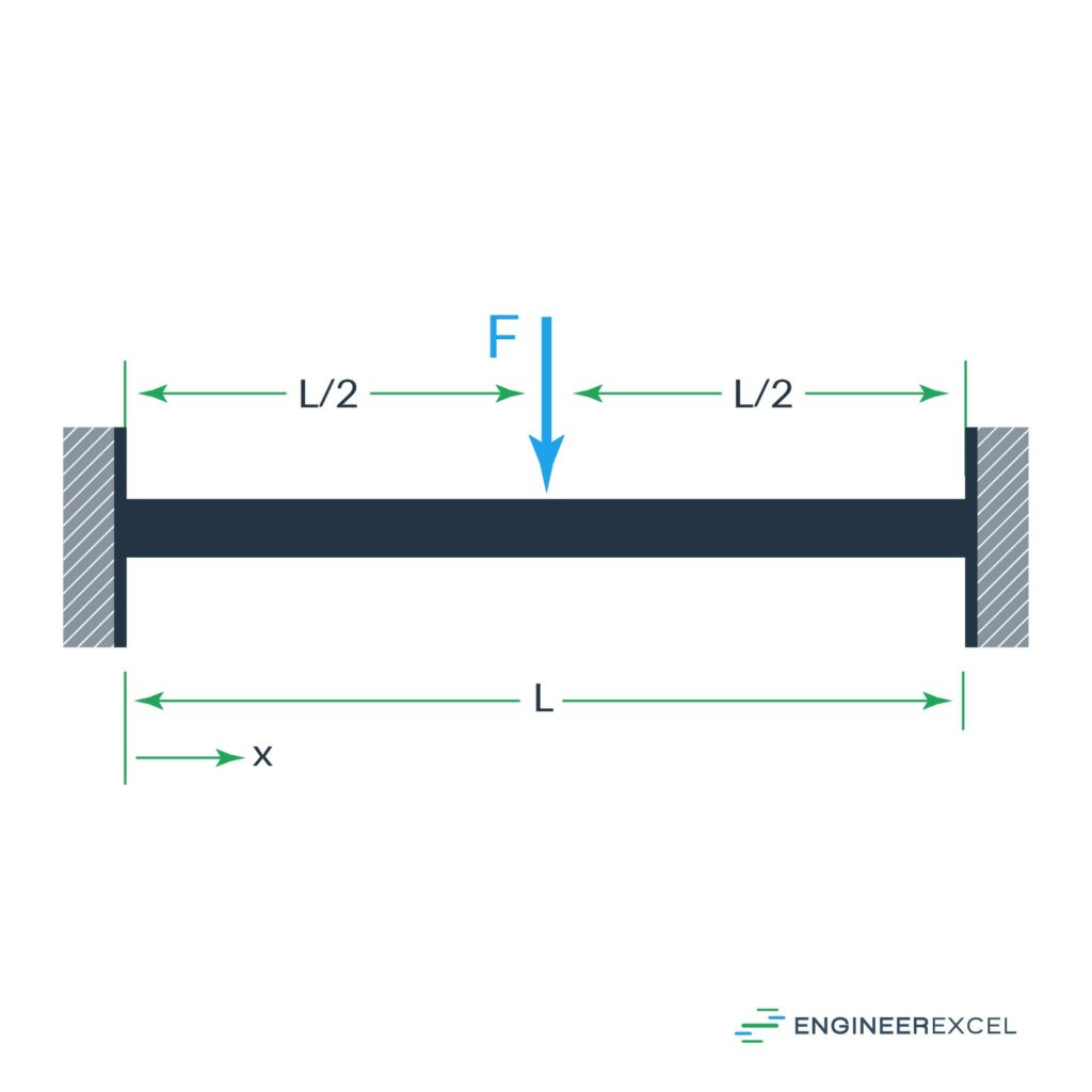
The deflection of the beam can be calculated using the following equation:

Fixed-Fixed Beam with Uniform Distributed Load
The other fixed-fixed beam deflection is the deflection due to a uniformly distributed force, as shown below:
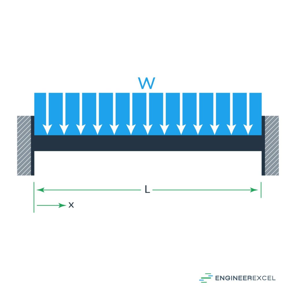
The deflection of the beam can be calculated using the following equation:

Differential Beam Deflection Calculation
Another method for calculating the deflection of a beam involves using the deflection curve’s differential equation to evaluate the beam’s bending behavior. An overview of this method is provided here, however, the specific details are beyond the scope of this introduction.
This method uses a general equation and can be applied to any combination of forces and moments applied at any point along a beam. The equation used is:

where:
- v is the deflection of the beam (m)
- d2v/dx2 is the second derivative of the deflection with respect to the position along the beam
- M is the bending moment along the beam as a function of the position (N∙m)
The bending moment at each section of the beam is calculated as a function of x. Then, each function is integrated twice to solve for EIv. System constraints are used to create a system of equations, which can be solved to determine the constants of integration. Finally, the individual equations can be used to determine the deflection v as a function of x.
Beam Deflection Application
By calculating the deflection of a beam subject to a force or a moment, an appropriate material can be selected for a specific application. The shape of a beam will determine its cross-sectional moment of inertia. Using this with the Young’s modulus of a material and the bending requirements, the beam system can be optimized.