
In a typical pressurized piping system, the entire cross-section of the conduit is occupied by fluid and flow is driven primarily by a pressure difference. However, in certain cases like drains and sewers, the conduit’s cross-section is filled only up to a specific depth. These flows, referred as partially full pipe flows, are explored in this article, covering their characteristics and calculation methods.
Partially Full Pipe Flow
Partially full pipe flow refers to the movement of fluid in a pipe that is not completely filled. As opposed to a fully developed pipe flow where the pipe is entirely occupied by the fluid, the channel in a partially full pipe flow is filled only up to a specific depth, as shown in the figure below.
When a pipe is partially filled with fluid, the flow can be treated similar to an open channel flow. This is because the liquid inside the pipe has a free surface, similar to open channels. The main distinction is that closed conduit flows have an enclosed top width, whereas open channels have one side exposed to the atmosphere.

Elevate Your Engineering With Excel
Advance in Excel with engineering-focused training that equips you with the skills to streamline projects and accelerate your career.
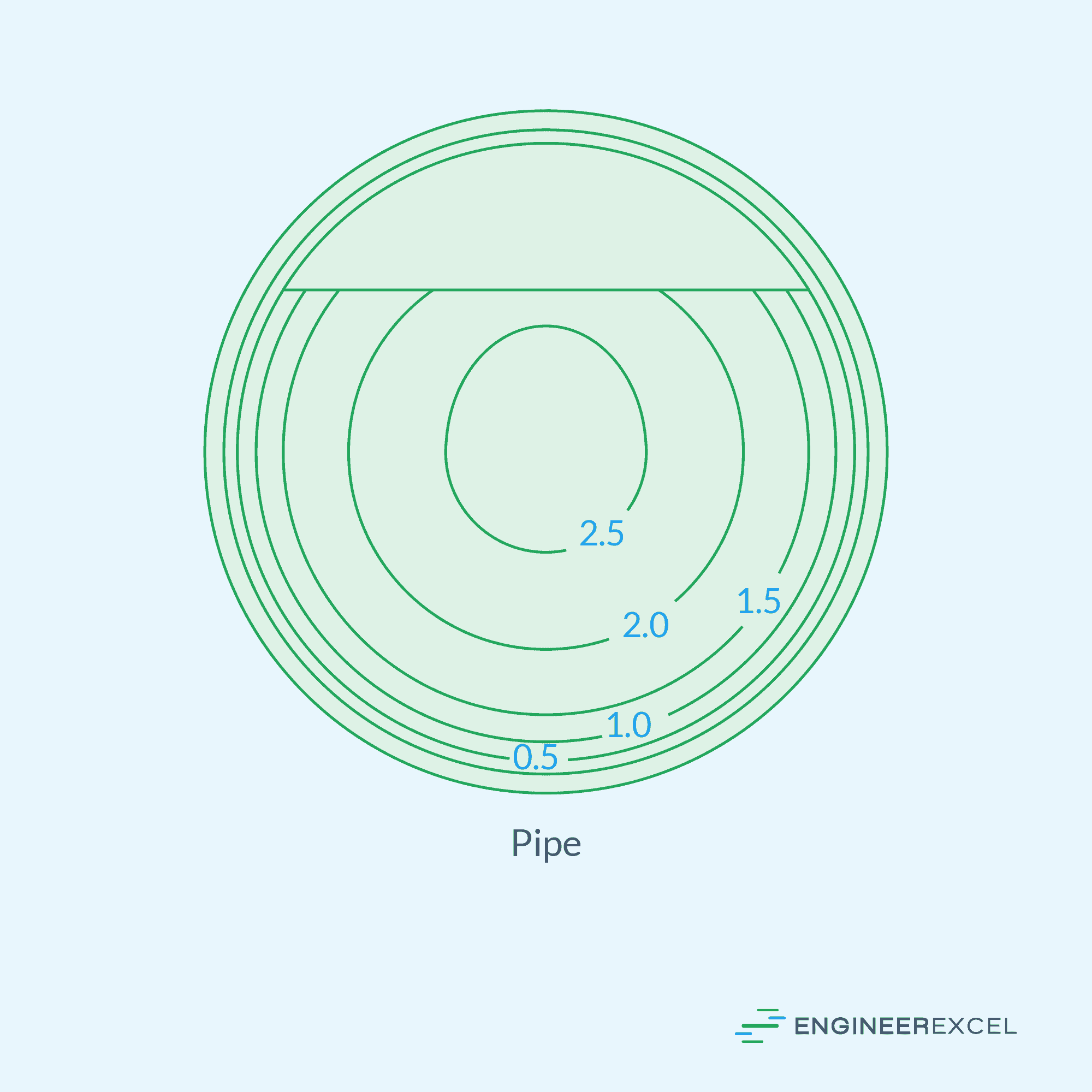
Provided that the pipe is not pressurized, the flow is primarily driven by gravity, similar to the flow in a river or canal. The velocity of the fluid is generally lowest near the surface of the pipe and increases towards the free surface and the center of the pipe. This pattern is demonstrated in the diagram of measured iso-velocity contours in a partially full pipe flow below.
Partially Full Pipe Flow Calculations
Partially full pipe flows can be analyzed using the same principles and equations of open channel hydraulics, which utilize both the Manning’s Equation and the Continuity Equation.
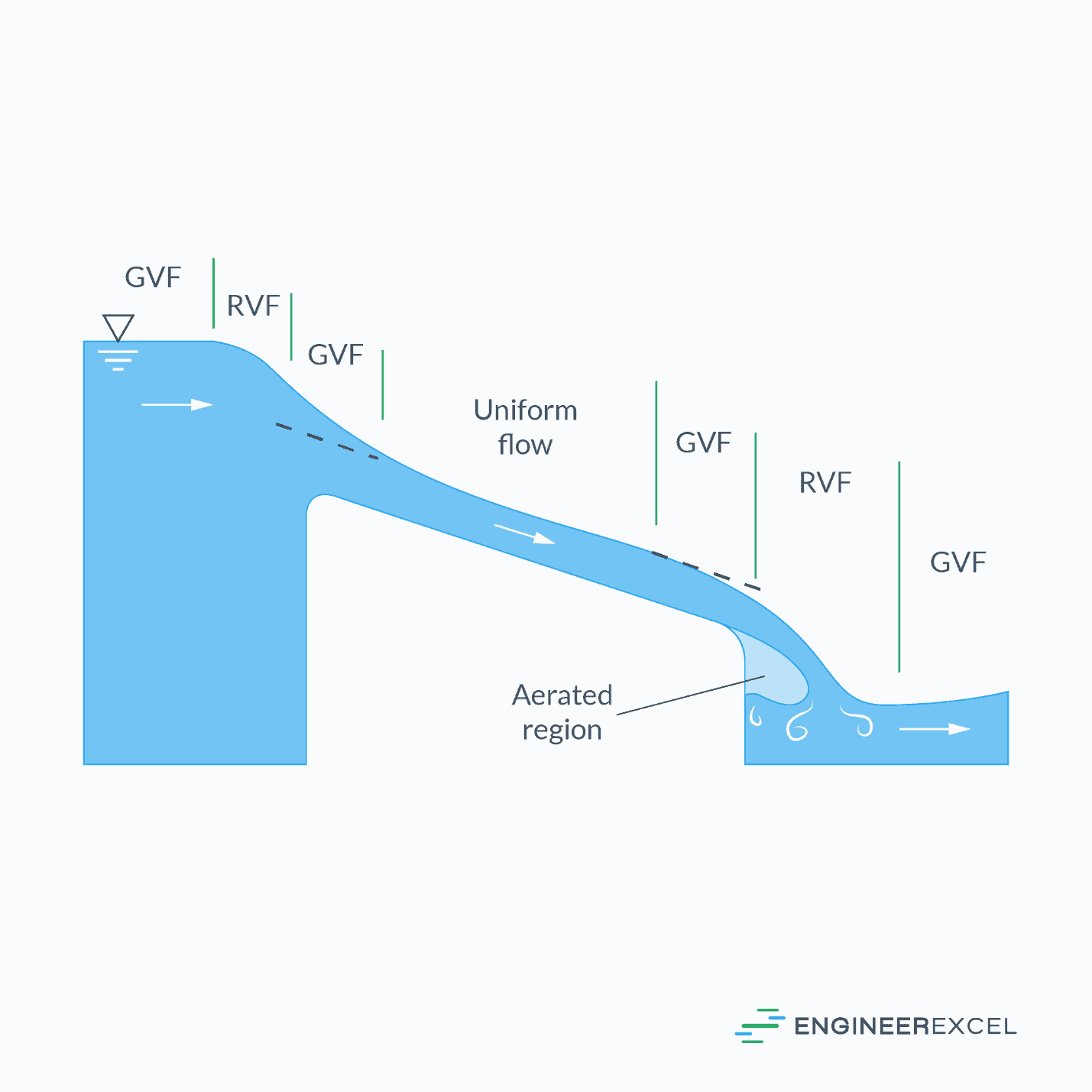
For computational purposes, it is commonly assumed that the flow is uniform. Uniform flow occurs when the flow velocity, water depth, and other properties remain relatively constant along the pipe. In uniform flow, the slope of the water surface and the bottom of the channel or pipe are parallel, as illustrated in the figure below.
The Manning Formula
The Manning formula, derived from the Chézy formula, is the most widely used equation for conducting uniform open channel flow calculations. It has two forms: one in SI units and the other in English units.
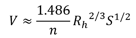
The SI unit form of the Manning formula for calculating the uniform flow velocity is as follows:
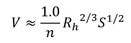
Where:
- V = fluid velocity [m/s]
- n = Manning roughness coefficient [unitless]
- Rh = hydraulic radius [m]
- S = slope of the channel [unitless]
On the other hand, the English unit form of the same formula is as follows:
Where:
- V = fluid velocity [ft/s]
- Rh = hydraulic radius [ft]
Note that the Manning formula is not dimensionally consistent and is just an approximation; hence, the symbol . Moreover, the slope of the channel, S, can be calculated by finding the tangent of the angle formed between the bottom of the channel and the horizontal. A positive slope indicates downhill flow.
Manning Roughness Coefficient, n
The Manning roughness coefficient, also known as Manning’s roughness factor, is a dimensionless value used to describe the resistance to flow within a channel. Its value mainly depends on the roughness of the conduit; however, it is also affected by the depth of the flow up to an extent. It is determined through empirical field observations and laboratory experiments.
Below is a table listing the experimental values of the Manning roughness coefficients for various common channels and conduit materials.
Hydraulic Radius Of A Partially Full Pipe
In general, the hydraulic radius of a channel can be determined by dividing the cross-sectional area of the flow perpendicular to the flow direction, by the wetted perimeter. In mathematical form:
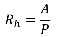
Where:
- A = cross-sectional area of the flow [m2 or ft2]
- P = wetted perimeter [m or ft]
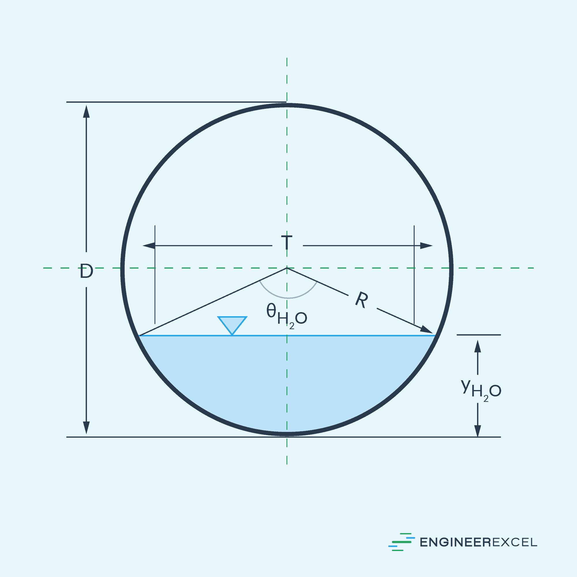
For a partially full circular pipe, consider the cross-sectional diagram shown below.
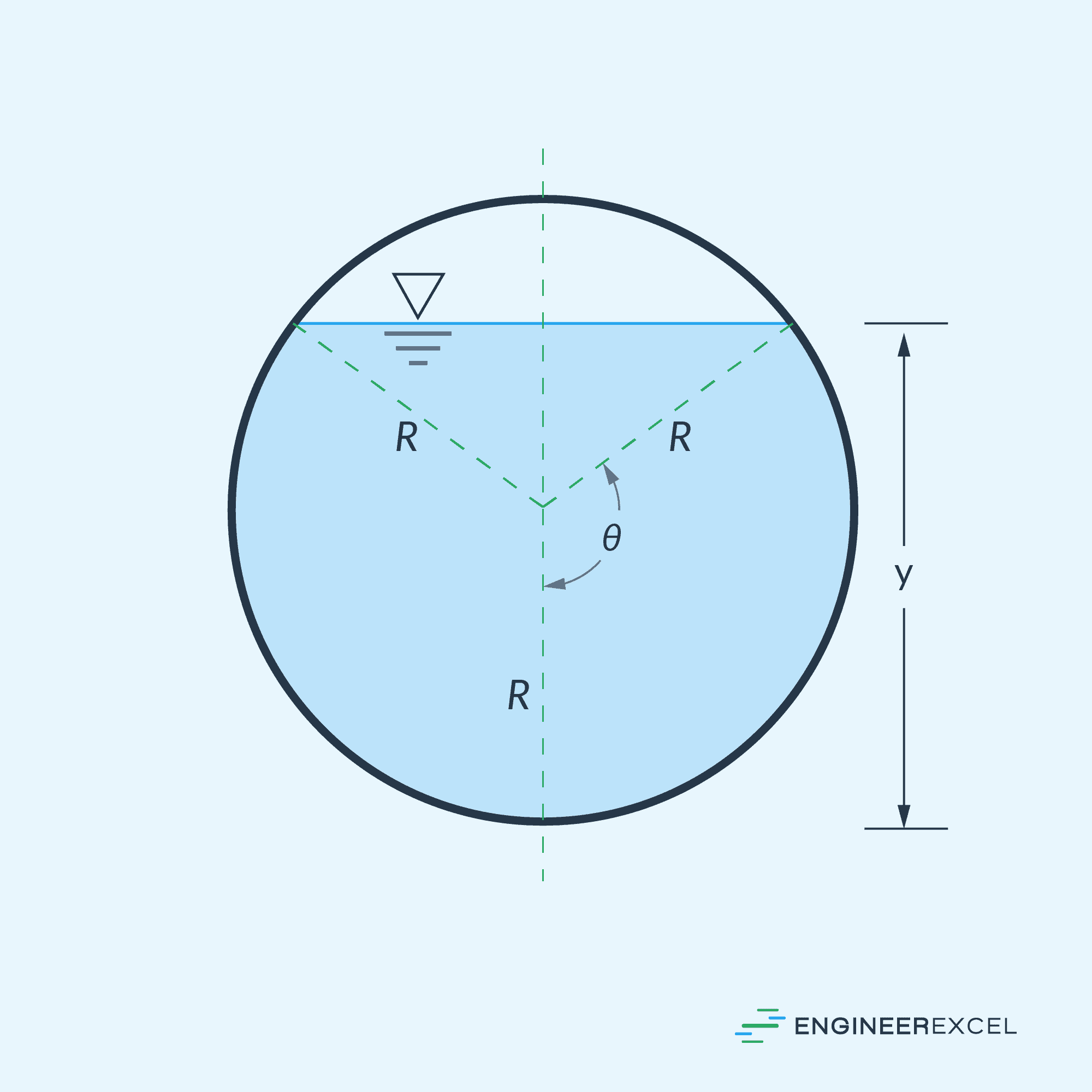
Based on the diagram above, the cross-sectional area of a fluid flowing through a partially full circular pipe can be calculated using the formula:
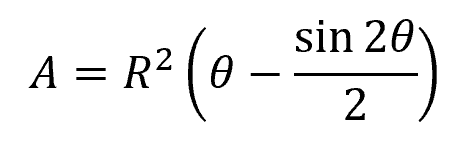
Where:
- R = radius of the pipe [m or ft]
- θ = angle between the vertical and the radial line to the edge of the free surface [deg or rad]
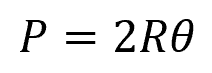
Moreover, the wetted perimeter can be calculated using the formula:
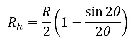
Substituting the equations for the area and wetted perimeter above, the formula for the hydraulic radius of a partially full circular pipe flow becomes:
Flow Velocity In Partially Full Pipe
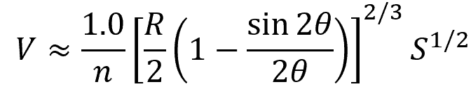
The above formula for hydraulic radius can be substituted into the Manning formula to obtain the flow velocity in a partially full circular pipe.
In SI unit form, the formula becomes:
Where:
- V = flow velocity [m3/s]
- R = radius of the pipe [m]
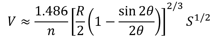
In English unit form, the formula becomes:
Where:
- V = flow velocity [ft3/s]
- R = radius of the pipe [ft]
Flow Rate in Partially Full Pipe
The flow rate in a partially full circular pipe can be obtained by multiplying the Manning formula with the cross-sectional area of the flow.
In SI units, the flow rate for a partially full circular pipe can be calculated using the following formula:
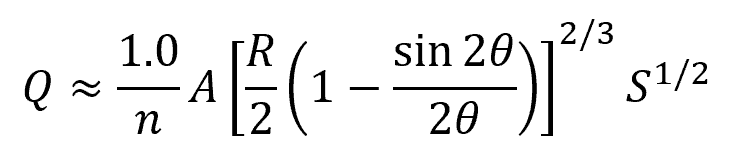
Where:
- Q = flow rate [m3/s]
- A = cross-sectional area of the flow [m2]
In English units, the same formula can be written as:
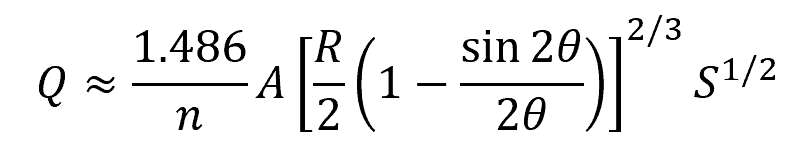
Where:
- Q = flow rate [ft3/s]
- A = cross-sectional area of the flow [ft2]
Maximum Flow Rate And Velocity In Partially Filled Pipe
Assuming a constant Manning roughness coefficient and slope of conduit, the fluid velocity and flow rate profiles can be plotted against the depth of flow, as shown in the graph below.
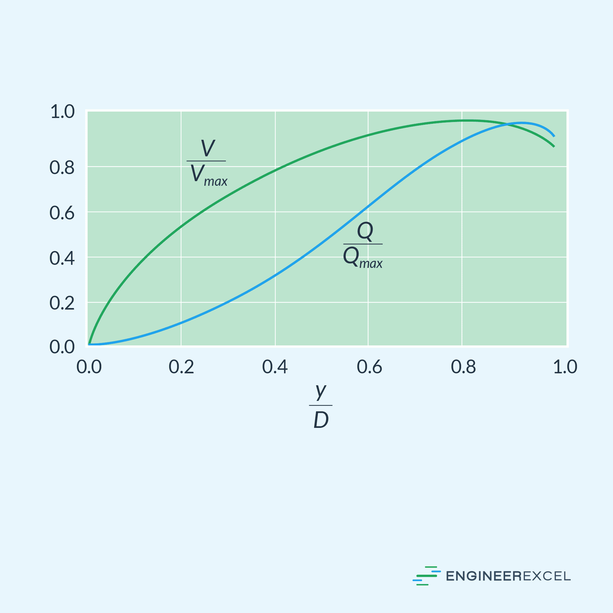
Based on the graph above, the maximum fluid velocity in a partially filled circular pipe can be calculated using the following formulas:
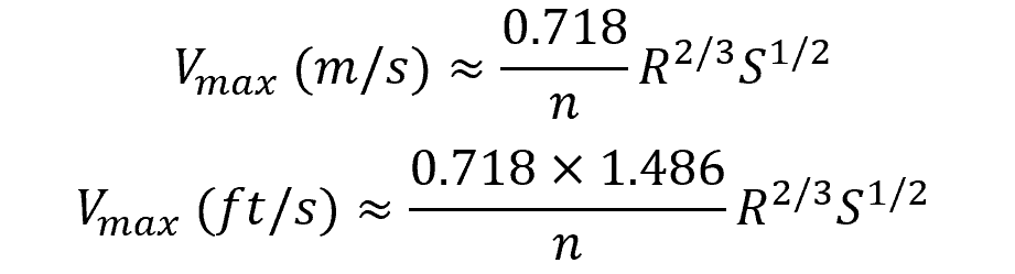
This maximum fluid velocity happens at θ = 128.73° and y = 0.813D.
On the other hand, the maximum flow rate can be calculated using the following formulas:
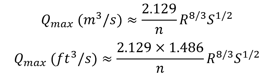
This maximum flow rate happens at θ = 151.21° and y = 0.938D.
It is worth noting that the maximum velocity in a partially filled pipe exceeds that of a fully running pipe by 14 percent, as depicted in the graph above. Likewise, the maximum flow rate is 8 percent higher. However, these differences are somewhat insignificant since pipes operating near full capacity tend to experience slightly unstable flow.
Full Pipe vs Partially Full Pipe Flow
A flow in a partially filled pipe differs from a flow in a fully filled pipe in significant ways. The primary difference between the two is that in a fully filled pipe, the flow is driven primarily by a pressure difference. In contrast, a partially filled pipe is treated similar to open-channel flow, where the flow is only partially bounded by the surface of the conduit and the fluid movement is primarily driven by gravity.
In the case of a fully filled pipe flow, all the principles of boundary layer theory apply, and the flow can be either laminar or turbulent depending on the flow velocity. However, in the case of a partially filled pipe flow, there is a presence of free surface and the principles of open channel hydraulics apply.
The presence of the free surface both helps and complicates the analysis.
It helps because the pressure can be assumed constant along the free surface. Unlike fully filled pipe flow, the pressure gradient is not a direct factor in a partially full pipe flow. The balance of forces in such a flow is confined to gravity and friction.
However, the free surface also complicates the analysis because its shape is not known in advance. The depth profile of the free surface changes with conditions and must be computed as part of the problem, especially in unsteady problems involving wave motion.