
The venturi meter is a type of flowmeter that measures flow rate on the basis of differential pressure, which results from the velocity changes that occur as the fluid flows through a venturi tube.
In this article, we will take a closer look at the various components that make up the venturi meter and their functions.
What is a Venturi Meter
A venturi meter is a device used to measure the flow rate of a fluid in a pipe. It works on the principle of the venturi effect, which is a phenomenon in fluid dynamics where a change in the cross-sectional area of a flow path leads to a change in fluid pressure.
A typical configuration of the venturi meter is shown in the diagram below.

Elevate Your Engineering With Excel
Advance in Excel with engineering-focused training that equips you with the skills to streamline projects and accelerate your career.
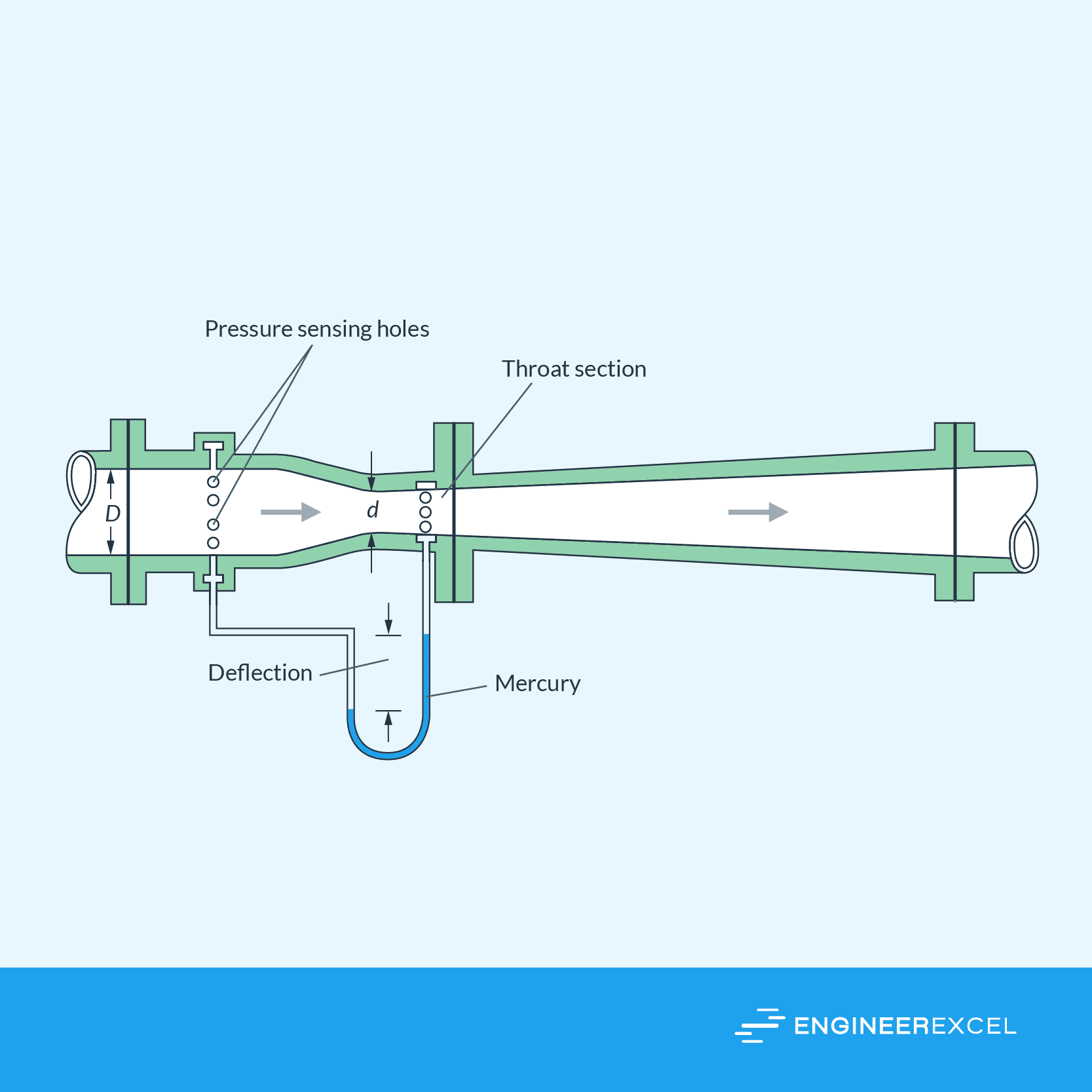
As the fluid enters the venturi meter, it passes through a converging section, called the inlet, which narrows down. This causes the fluid velocity to increase and pressure to decrease. The point of minimum cross-sectional area in the venturi meter is called the throat, where fluid velocity is at its maximum and pressure is at its minimum.
After the throat, the fluid moves through a diverging section, or outlet, where the cross-sectional area increases, causing the fluid velocity to decrease and pressure to increase. Meanwhile, pressure taps located at the inlet, throat, and outlet record the pressure at these points in the meter.
By measuring the difference in pressure between the inlet and the throat, you can determine the fluid’s flow rate using the following equation:
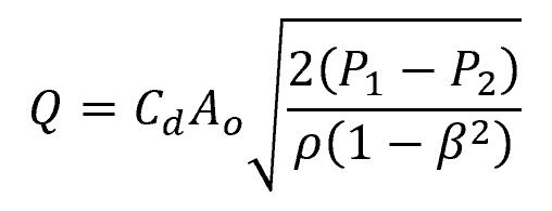
Where:
- Q = flow rate [m3/s]
- Cd = discharge coefficient of the venturi meter [unitless]
- Ao = area of the throat [m2]
- P1 = pressure at the inlet [Pa]
- P2 = pressure at the throat [Pa]
- ρ = density of the fluid [kg/m3]
- β = ratio of the throat diameter to inlet diameter [unitless]
The discharge coefficient is a correction factor that accounts for the losses due to friction and flow geometry. Its value is determined experimentally and generally depends on both the throat-inlet diameter ratio and the Reynolds number of the flow.
Due to its efficient design, Venturi meters exhibit high discharge coefficients that typically range between 0.95 and 0.99, with the higher values observed at higher Reynolds numbers. In cases where specific data is unavailable, a discharge coefficient of approximately 0.98 can be assumed for Venturi meters.
Venturi meters are versatile devices with numerous applications across different industries. Their accuracy, reliability, and ease of use have made them a popular choice in flow measurement applications, such as in the water supply and treatment industry, oil and gas industries, chemical and petrochemical industries, and power generation.
Parts of Venturi Meter
A venturi meter consists of several components that work together to accurately measure fluid flow. These include the inlet cylinder, converging cone, throat, diverging cone, pressure connections, vent, drain, inspection hole, and support structure.
Inlet Cylinder
The inlet cylinder is where the fluid enters the Venturi meter. It has a large diameter to accommodate the flow and helps in reducing the initial pressure drop. This also ensures a smooth transition for the fluid entering the converging cone.
Converging Cone
The converging cone is the section where the diameter gradually decreases, causing an increase in fluid velocity. This increase in velocity results in a decrease in pressure, according to Bernoulli’s principle. The cone’s angle is crucial as it directly impacts pressure recovery and accuracy.
Throat
The throat is the narrowest part of the Venturi meter and is where the fluid reaches its highest velocity. It is the point at which the flow rate is measured by calculating the pressure difference between the inlet and throat sections. This pressure difference allows for the determination of the flow rate.
Diverging Cone
As the fluid exits the throat, it enters the diverging cone. The cone’s diameter gradually increases, slowing the fluid’s velocity and allowing pressure to partially recover. This pressure recovery means that the overall pressure drop across the Venturi meter is reduced, minimizing energy loss.
Pressure Connections
Pressure connections are crucial in measuring the pressure difference between the inlet and throat sections. They are typically installed at the sides of the inlet and throat, connecting to a manometer or differential pressure transmitter. This pressure difference allows for the calculation of the flow rate.
Vent and Drain
Vents and drains are essential for the proper maintenance and operation of a Venturi meter. They facilitate the release of trapped gases or the removal of accumulated liquids, ensuring accurate readings and reducing the risk of meter failure.
- Vent: Allows trapped gases to escape, maintaining a stable pressure reading.
- Drain: Drains accumulated liquids from the meter, preventing incorrect measurements.
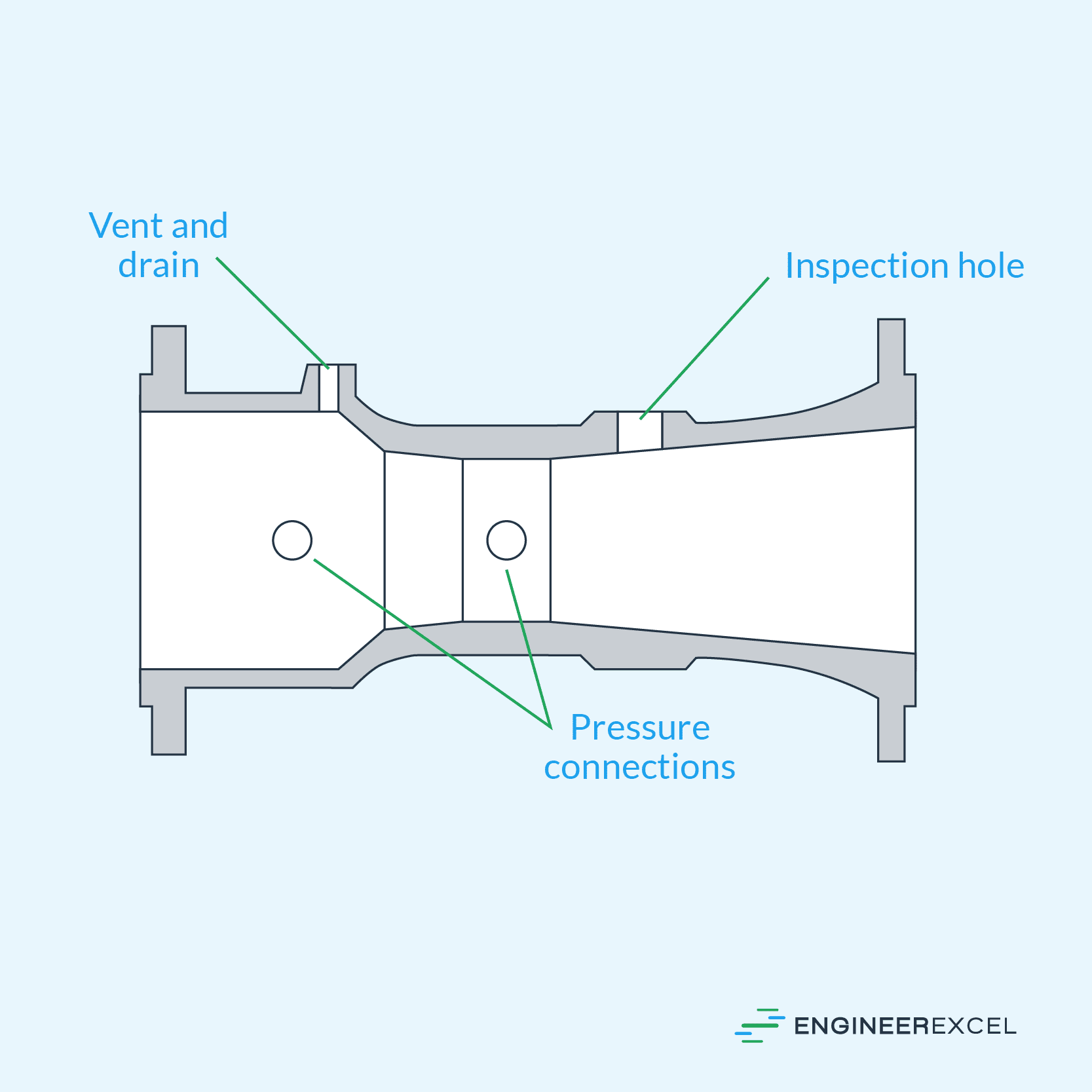
Inspection Hole
An inspection hole is provided in some Venturi meters to enable visual inspection and maintenance. It is usually located on the side of the meter, allowing technicians to check for deposits, corrosion, or damage. Regular inspection helps ensure the accuracy and longevity of the Venturi meter.
Support Structure
Venturi meters are typically installed in pipelines using a support structure that holds the Venturi tube in place and ensures proper alignment within the pipe.