
Nozzle meters are a type of differential flowmeter that uses a nozzle to create pressure difference in a pipe flow, which can be measured to determine flow rate. They are commonly used in measuring non-viscous fluids such as steam and other gases, as well as some liquid applications where the use of an orifice meter is not probable.
In this article, we will discuss the components of a nozzle meter, its components, types, flow rate calculation, and applications.
What is Nozzle Meter
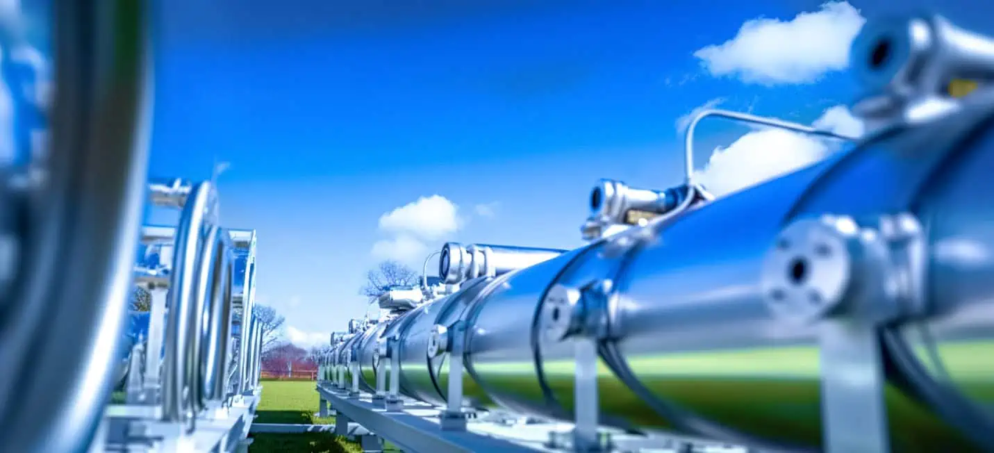
A nozzle meter, also commonly called flow nozzle, is a type of differential flowmeter that consists of a converging section followed by a cylindrical throat, specifically designed to create a pressure difference between the inlet and throat sections. As the fluid flows through the nozzle meter, its velocity increases and pressure decreases simultaneously. This pressure difference can be measured and used to calculate the flow rate of the fluid passing through the nozzle meter.
The diagram below shows the basic structure of a flow nozzle.

Elevate Your Engineering With Excel
Advance in Excel with engineering-focused training that equips you with the skills to streamline projects and accelerate your career.
Components of Nozzle Meter
Nozzle Throat
The nozzle throat is the narrowest part of the meter and serves as the key point of flow measurement. The fluid velocity increases in the nozzle throat, resulting in a pressure drop across it. This pressure drop is proportional to the flow rate and can be calculated with the help of Bernoulli’s equation.
Converging Section
The converging section is the first part of the nozzle meter where the fluid enters. It has a gradually decreasing diameter, which helps accelerate the fluid towards the nozzle throat. The convergent angle is selected carefully to ensure minimal pressure loss and maintain flow consistency.
Pressure Taps
Pressure taps enable flow measurements by connecting pressure transducers to the nozzle meter. These are typically located at specified distances upstream and downstream of the nozzle throat. The pressure taps measure the pressure difference between these two points, which can then be used to calculate the flow rate.
Pipe Connections
Pipe connections facilitate the integration of the nozzle meter within the larger fluid system. Common types of pipe connections include flanges, holding rings, and welded joints. The choice of connection type depends on factors such as pipeline size, material, operating pressure, and temperature.
Flow Straightener
A flow straightener aims to reduce flow disturbances and minimize turbulence before the fluid enters the nozzle meter. This component typically consists of a series of parallel plates or tubes arranged perpendicularly to the flow direction. By stabilizing the flow profile, flow straighteners ensure accurate and reliable flow measurements.
Other Accessories
Other accessories may be present in a nozzle meter system to improve performance and functionality. These may include temperature and pressure sensors for monitoring operating conditions and allow for compensation in flow calculations based on fluid properties, as well as bypass valves for maintenance, cleaning, or calibration purposes.
Types of Nozzle Meters
ISA 1932 Nozzles
The ISA 1932 nozzle is a flow nozzle designed to meet the International Society of Automation (ISA) standard for nozzle dimensions and tolerances. It is commonly used in high-pressure and high-temperature applications with line sizes ranging from 2 to 20 inches.
The ISA 1932 nozzle does not rely on a sharp edge to maintain accuracy, which can deteriorate over time. This feature provides excellent long-term accuracy with less wear, reducing the possibility of distortion. Thus, it is often used for high-accuracy flow measurement in power plant applications.
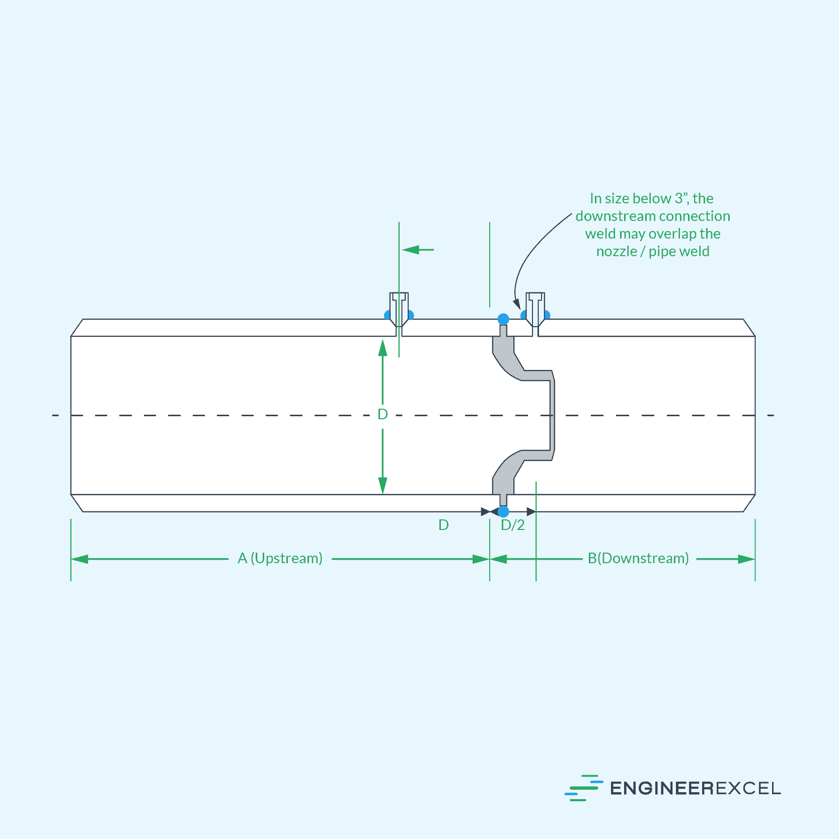
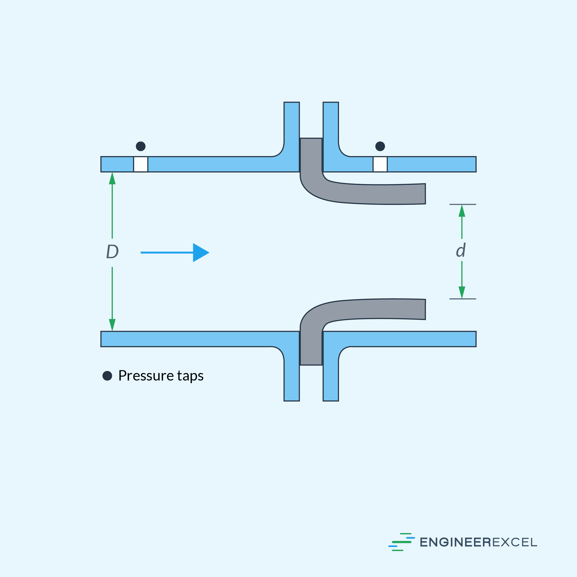
ASME Long Radius Nozzles
The Long Radius Nozzle is manufactured according to the US Standard ASME. There are two types of long radius nozzles: High Beta nozzles (0.25 ≤ β ≤ 0.8) and Low-Beta nozzles (0.20 ≤ β ≤ 0.5).
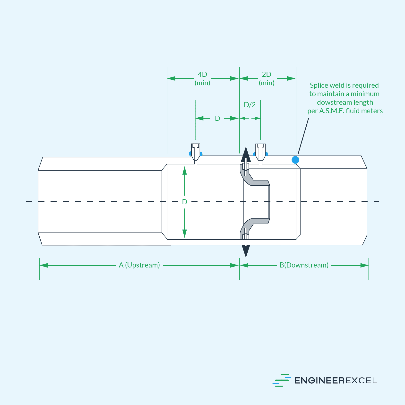
Long Radius Nozzles have a smooth elliptical inlet leading to a throat section with sharp outlet. The length of the Long Radius Nozzle depends on the Beta-Ratio, with lower ratios resulting in shorter lengths.
The upstream/downstream tap locations are D and D/2 from the inlet face of the nozzle. Depending on requirements, the tappings can have a butt or socket weld, screw thread, or flange connection.
Flow Rate Calculation Using Nozzle Meter
To calculate the flow rate, the pressure difference before and after the orifice is measured, using devices like differential pressure transmitters or manometers, and used as input for the following calculation:
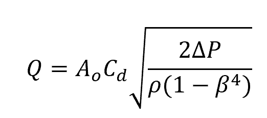
Where:
- Q = flow rate [m3/s]
- Cd = discharge coefficient [unitless]
- Ao = cross-sectional area of the throat [m2]
- ΔP = pressure difference across the nozzle [Pa]
- ρ = fluid density [kg/m3]
- β = beta ratio between throat diameter and pipe diameter [unitless]
The discharge coefficient (Cd) is a dimensionless factor that accounts for any losses due to friction and turbulence. In general, its value is dependent on the beta ratio and Reynolds number. For nozzle meters, the experimentally determined data for discharge coefficients can be expressed as:
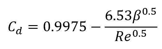
Where:
- Re = Reynolds number [unitless]
This equation is valid for β values between 0.25 and 0.75, and Reynolds numbers between 104 and 107. For flows with high Reynolds numbers beyond 30,000, the discharge coefficient of a nozzle meter can be assumed to be equal to 0.96.
Nozzle Meter Applications
Nozzle meters are often used for high-pressure and high-velocity flow measurements. They are particularly useful for measuring non-viscous fluids such as steam and other gases, as well as some liquid applications where erosive and abrasive material is present, which would otherwise deteriorate the bore edge of an orifice meter.
In terms of pressure loss, accuracy, and cost, nozzle meters are in between orifice meters and venturi meters. Nozzles offer a more streamlined fluid flow than orifice meters, but less streamlined than venturi meters.