
When designing or analyzing piping systems, engineers often need to consider the pressure losses caused by the different piping components in order to properly size the pump and gauge the performance of the system. One of the methods for quantifying the pressure loss caused by a piping component is by obtaining its equivalent length.
This article explores the concept of equivalent length, focusing particularly on the equivalent length of ball valves.
Equivalent Length of Ball Valves
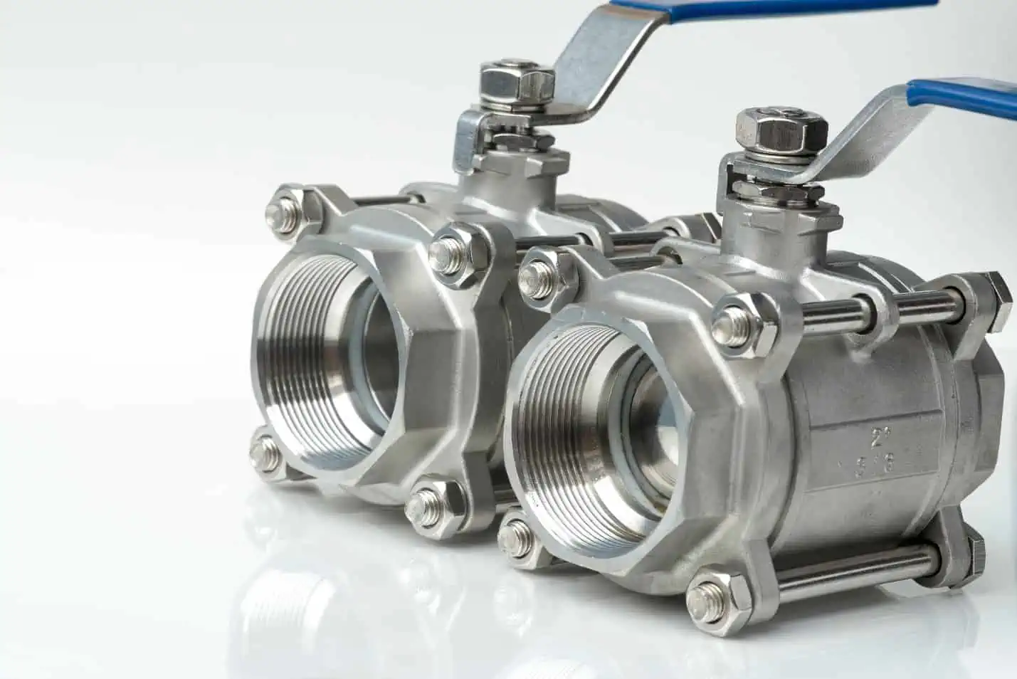
A ball valve is a type of valve that controls pipe flow using a sphere with a center hole. It is typically operated with an actuator or a lever handle, which runs parallel to the pipeline when the valve is open and perpendicular when closed.
Because of its spherical geometry, the ball valve is able to create a tight seal and can quickly shut off the flow with just a 90-degree turn. This makes it highly effective for emergency shutoff applications.

Elevate Your Engineering With Excel
Advance in Excel with engineering-focused training that equips you with the skills to streamline projects and accelerate your career.
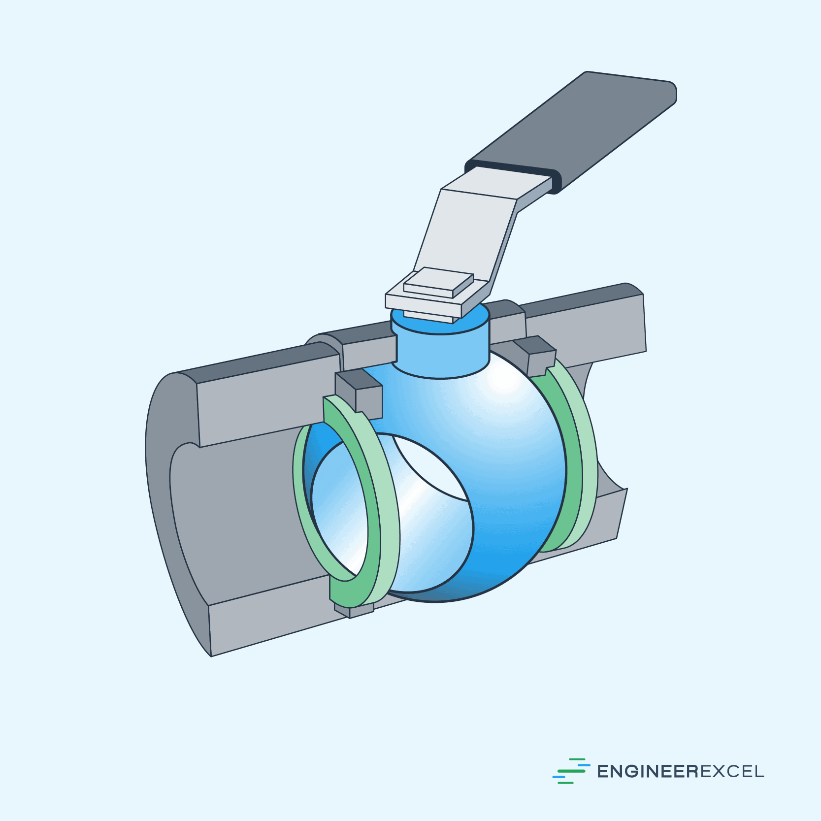
The diagram below shows a typical ball valve.
Just like any other valve or pipe component, ball valves contribute to the total pressure loss in a piping system. One of the ways to quantify this pressure loss is by obtaining its equivalent length.
Simply put, the equivalent length of a ball valve refers to the length of straight pipe that would hypothetically cause the same pressure drop as the ball valve itself. By obtaining the equivalent length, the pressure loss caused by the ball valve can be analyzed in the same terms as the pipes.
The table below shows the equivalent lengths (in feet) of a typical ball valve. These values were obtained from Rules of Thumb for Chemical Engineers by Carl Branan.
It has been experimentally found that, for most valves and fittings (including ball valves), the ratio of equivalent lengths to diameters, Le/D, shows minimal variation across a range of sizes. For instance, in the table above showing the equivalent lengths of a typical ball valve, the Le/D ratio falls within the range of 8 to 12.
However, note that these values may vary depending on the ball valve design and material used for the component. Although they can be useful for shortcut calculations during preliminary studies or troubleshooting, it is still best to refer to the manufacturer of the component for more accurate data.
To better grasp the values presented in the table, it is essential to understand the general concept of equivalent lengths.
Understanding the Concept of Equivalent Length
In a typical piping system, pressure losses can be divided into two categories: major losses and minor losses. Major losses occur as a result of friction between the fluid and the pipe wall as it flows through the pipe. On the other hand, minor losses are caused by changes in the flow path or velocity.
Pressure losses associated with valves, fittings, and other geometric changes along the pipeline are considered as minor losses. The minor loss of a component can be calculated using the following formula:
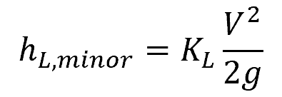
Where:
- hL, minor = head loss caused by a valve or fitting [m]
- KL = loss coefficient of the valve or fitting [unitless]
- V = fluid velocity [m/s]
- g = gravitational acceleration [m/s2]
The loss coefficient is a dimensionless parameter used to characterize the effect of the component’s geometry and material to pressure loss. Since flow through valves and fittings is very complex, and a theoretical analysis is generally not plausible, loss coefficients are determined experimentally, usually by the manufacturers of the components.
Traditionally, after calculating the minor losses for each valve and fitting using the above formula, they are combined with the major losses to obtain the total pressure losses in the system. However, another approach is to use the concept of equivalent lengths. This method is based on the observation that both the major and minor losses are proportional to the velocity head.
The method of equivalent lengths involves converting the valves and fittings into equivalent lengths of straight pipe that would yield the same pressure loss. These equivalent lengths are then added to the actual length of straight pipes to obtain a hypothetical total length that would yield the same total pressure losses, as follows:
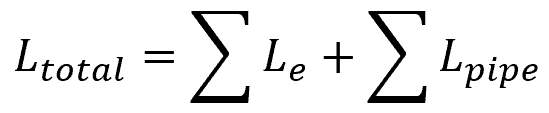
Where:
- Ltotal = hypothetical total length of pipe [m]
- Le = equivalent length of each valve and fitting [m]
- Lpipe = actual length of straight pipes [m]
Using the sum of the equivalent lengths of all components and the actual length of straight pipes, the total system head loss can be calculated using the same formula used for calculating major losses, as follows:
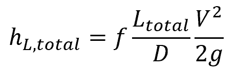
Where:
- hL,total = total system head loss [m]
- f = Darcy-Weisbach friction factor [unitless]
- D = pipe diameter [m]
The Darcy-Weisbach friction factor is a dimensionless quantity used to characterize the resistance of a fluid flowing through a pipe due to internal friction. Its value depends on the nature of the flow, the roughness of the pipe’s inner surface, and the Reynolds number.

Using the concept of equivalent lengths, the complex network of pipes and fittings in a system can be replaced by an equivalent length of straight pipe. This simplification allows engineers to use standard straight pipe flow equations and pressure drop calculations, making the analysis of the system much simpler.
In the early stage of a design, it is common to estimate the equivalent length of valves and fittings with a broad allowance. For instance, one may add 20% to the straight pipe length to account for the pressure losses caused by valves and fittings. However, once the design is finalized and the quantities of the valves and fittings are known, a more accurate calculation of the minor losses can be achieved using experimentally determined equivalent lengths for each of the components.
Equivalent Pipe Length Formula
Given a loss coefficient, the equivalent length of a valve or fitting can be calculated using the formula:
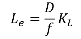
While there are published tables showing typical values for the equivalent lengths of ball valves, it is important to note that these values can vary not only based on the ball valve design and material but also on local flow conditions, as shown in the formula above. Hence, caution must always be exercised when using the method of equivalent lengths, as it has a tendency to oversimplify the analysis. It is always preferable to perform a detailed analysis in order to account for specific geometries and flow patterns, rather than rely on generic equivalent length values.