
Laminar flow through an annulus occurs when a fluid flows through a circular pipe with an annular space between the pipe and an inner cylinder. This phenomenon is widely studied and observed in various engineering applications, including heat exchangers, chemical reactors, and other industrial processes.
In this article, we explore the mechanics behind laminar flow through an annulus.
Laminar Flow Through an Annulus
Laminar flow through an annulus refers to the smooth and orderly movement of fluid through an annulus. This occurs in situations where the fluid’s viscosity dominates over its inertia.
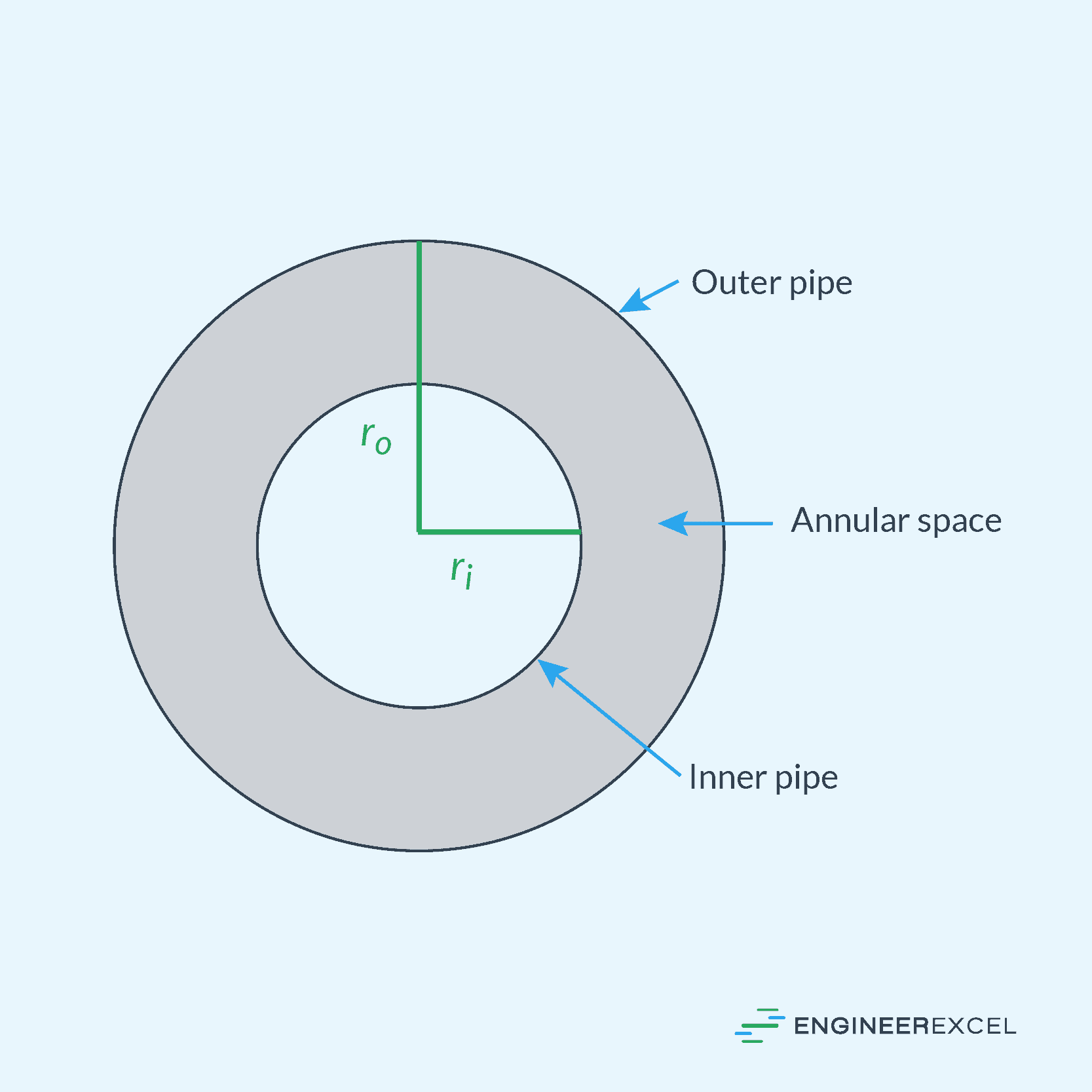
In general, an annulus is the region between two concentric circles. In the context of fluid dynamics, this is typically the space between two concentric cylindrical pipes, as shown in the diagram below.

Elevate Your Engineering With Excel
Advance in Excel with engineering-focused training that equips you with the skills to streamline projects and accelerate your career.
Laminar flow through annulus is a common setup in various industrial applications, where fluids flow between the inner and outer pipe walls. Compared to a normal pipe flow where the fluid only interacts with the pipe’s inner wall, flow through an annulus can be more complex to analyze because the behavior of the fluid is affected by the properties of both the inner and outer cylinders.
An annulus can be concentric or eccentric. However, for the purpose of this article, we will focus on the simplest type – the concentric annulus. This is characterized by an inner pipe that is perfectly centered within the outer pipe, creating an even annular space for laminar flow to occur.
Applications of Laminar Flow Through Annulus
Laminar flow through an annulus is an idealized representation of fluid flow in many important industrial processes.
For instance, in oil well drilling, a heavy drilling mud is circulated through the annular space around the drill pipe to transport the drilling debris to the surface. Such drilling muds are typically composed of a mixture of water or oil, clay and other minerals, and various chemical additives. The composition can vary depending on the specific drilling conditions, including the type of formation being drilled, the depth of the well, and environmental considerations.

Similarly, the extrusion of plastic tubes and pipes involves forcing molten polymer through an annular die, which requires precise control of laminar flow to ensure consistency in the final product.
Other examples of applications of laminar flow through annulus include the production of optical fibers, where a glass preform is melted and drawn through an annular orifice to create the fiber, and the design of certain types of filters, where fluids are passed through an annular space to remove impurities.
Velocity Profile of Laminar Flow Through a Concentric Annulus
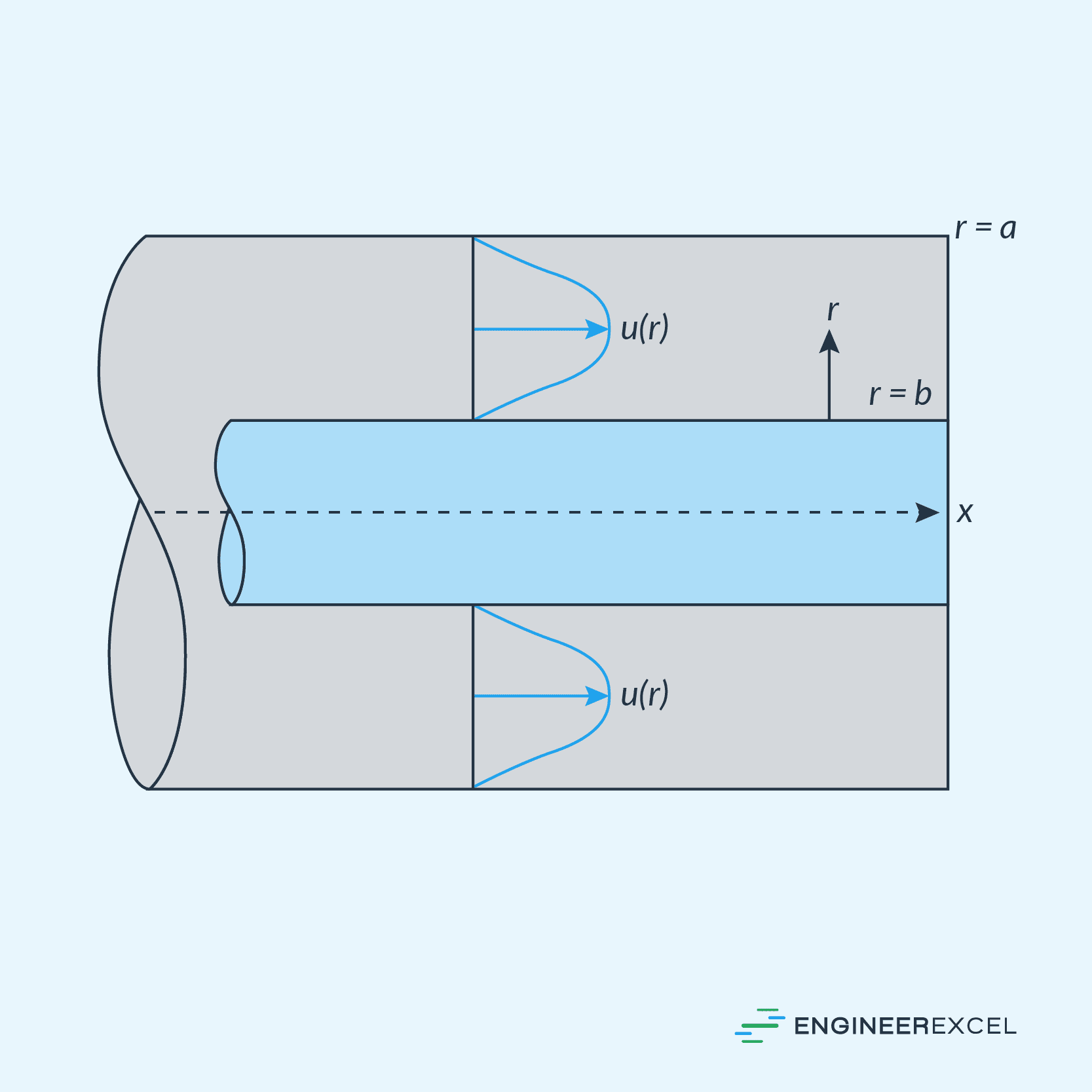
When a fluid flows through an annular region under laminar flow conditions (i.e., low flow rates and low Reynolds numbers), the velocity of the fluid varies across the annulus following a parabolic profile. It means that the fluid velocity is highest at the center of the annulus and gradually decreases as you move toward the inner and outer walls. This parabolic velocity distribution is a result of the no-slip boundary condition, where the fluid in contact with the walls of the annulus has zero velocity due to viscous effects.
The velocity profile resembles a parabola wrapped around in a circle to form a split doughnut, as shown in the diagram below.
Mathematically, this can be expressed as follows:
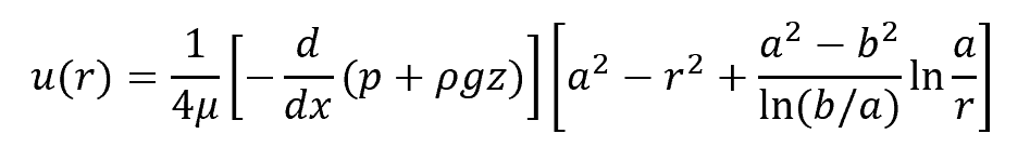
Where:
- u(r) = fluid velocity with respect to r [m/s]
- r = distance from the center [m]
- μ = dynamic viscosity [Pa-s]
- p = pressure [Pa]
- ρ = fluid density [kg/m3]
- g = gravitational acceleration [9.81 m/s2]
- z = vertical distance above a reference point [m]
- a = radius of the outer pipe [m]
- b = radius of the inner pipe [m]
Volumetric Laminar Flow Rate Through a Concentric Annulus
The velocity equation above can be integrated across the entire area of the annulus to determine the volumetric flow rate as follows:
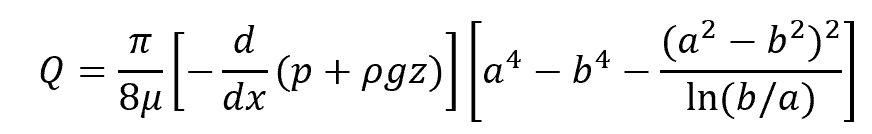
Where:
- Q = volumetric flow rate [m3/s]
Friction Loss in Laminar Flow Through Concentric Annulus
Like normal pipe flow, the head loss due to friction in laminar flow through a concentric annulus can be calculated using the Darcy-Weisbach equation as follows:
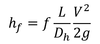
Where:
- hf = head loss due to friction [m]
- f = Darcy friction factor [unitless]
- L = length of conduit [m]
- Dh = hydraulic diameter of the conduit [m]
- V = average fluid velocity [m/s]
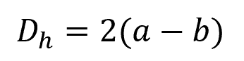
However, in this case, the hydraulic diameter is different. For a concentric annulus, the hydraulic diameter can be calculated using the following formula:
Moreover, the friction factor for laminar flow through a concentric annulus can be calculated using the following formula:
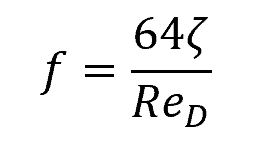
Where:
- ReD = Reynolds number [unitless]
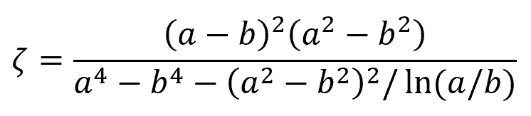
The dimensionless term ζ is a correction factor equal to:
In general, laminar annular flow becomes unstable at Reynolds numbers greater than 2000.