
Axial load refers to a force that is applied along the axis, or the central line, of a structural element, such as a column or a beam. This type of load results in compression or tension within the material, depending on the direction of the force relative to the axis.

In this article, we will discuss key considerations for engineering design related to axial load, including the calculation of axial stress and strain as well as the concept of critical load and buckling.
What is Axial Load
Axial load refers to the force applied along the longitudinal axis of a structural member, such as a beam, column, or shaft. It can either be compressive, where the force tends to shorten or compress the structure, or tensile, where the force acts to elongate or pull the structure apart.
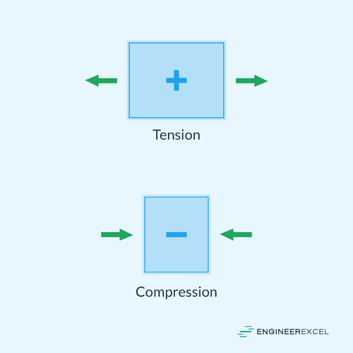
In general, axial load is considered positive if it is in tension and negative if it is in compression, as illustrated in the diagram below.

Elevate Your Engineering With Excel
Advance in Excel with engineering-focused training that equips you with the skills to streamline projects and accelerate your career.
Apart from the direct application of external force, axial load can also be caused by various factors. For instance, vertical loads due to the weight of structures, components, or materials can result in axial loads.
Additionally, changes in temperature can cause axial loads due to thermal expansion or contraction of materials. When a material expands or contracts, it may experience axial forces as it tries to accommodate the dimensional changes.
In practice, a structural member may experience a combination of several axial loads. Accounting for these loads in engineering design is important because they directly affect the structural stability and integrity of a component or structure. If not properly considered, axial loads can lead to buckling, deformation, or failure.
Axial Load Calculations
Axial Stress and Strain
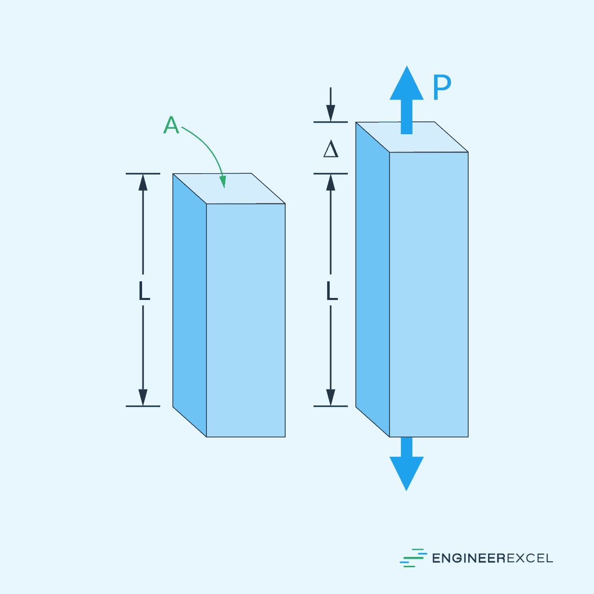
When an axial load is applied to a structure, it induces axial stress and strain along the length of the material.
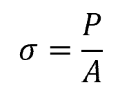
Axial stress is defined as the force per unit area acting on a material along its longitudinal axis. It represents the intensity of the internal forces within the material and is typically measured in Pascals (Pa).
This can be calculated using the following formula:
Where:
- σ = average axial stress [Pa]
- P = applied axial load [N]
- A = cross-sectional area of the structure [m2]
Typically, when a concentrated load is applied axially, it creates a highly nonuniform stress distribution and local stresses near the load. Nevertheless, the stress levels out to a nearly uniform distribution at a significant distance from the point of application.
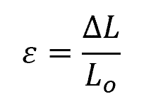
Axial strain (ε), on the other hand, quantifies the amount of deformation or elongation the material undergoes under the applied axial load. It is the ratio of the change in length to the original length of the material, expressed as:
Where:
- ε = axial strain [unitless]
- ΔL = change in length of the structure [m]
- Lo = original length of the structure [m]
The relationship between stress and strain is characterized by the material’s modulus of elasticity, also known as Young’s modulus (E). Young’s modulus represents the stiffness of the material and is defined as the ratio of stress to strain in the elastic region of deformation, as shown by the following formula:
Where:
- E = Young’s modulus [Pa or psi]
In the early stages of axial loading, materials typically exhibit linear elastic behavior, meaning that stress and strain are directly proportional within this range. As the load increases, the material may undergo plastic deformation, where the relationship between the stress and strain deviates from the linear trend, and permanent deformation occurs. The point at which plastic deformation begins is known as the yield point.
Critical Load and Buckling
When designing structures subjected to axial loads, it is crucial to consider the possibility of buckling. Buckling is a phenomenon in which the structure loses its stability and suddenly bends or collapses when subjected to external forces. This is particularly important to consider in long, slender columns.
The critical load is the threshold load at which a structure starts to buckle. In order to calculate the critical load, the Euler’s formula can be used:
Where:
- Pcr = critical load [N]
- E = elastic modulus of the material [Pa]
- I = moment of inertia of the cross-sectional area [m4]
- L = unsupported length of the member [m]
- K = effective length factor [unitless]
The value of the effective length factor depends on the type of support at the ends of the structure. For pinned ends, for example, the value of K is equal to 1. For fixed ends, it is equal to 0.5. And for a column with pinned and fixed ends, it is equal to 0.7.
The associated average normal stress in the column just before the column buckles is called the critical stress. This stress is in the elastic region and it can be calculated using the following formula:
Where:
- σcr = critical stress [Pa]
- r = smallest radius of gyration of the column [m]