
As a common structural member, a T beam is often utilized in engineering design. To optimize the design of a T beam, it is necessary to understand how the beam will respond to various expected loads. A key response to loading will be the bending about the axes. To determine the bending response of a T beam, the moments of inertia about the x-axis and the y-axis are needed.
T Beam Moment Of Inertia About X-Axis
To calculate the moment of inertia of a T beam about the x-axis, it is necessary to divide the section into two pieces, as shown in the following figure:
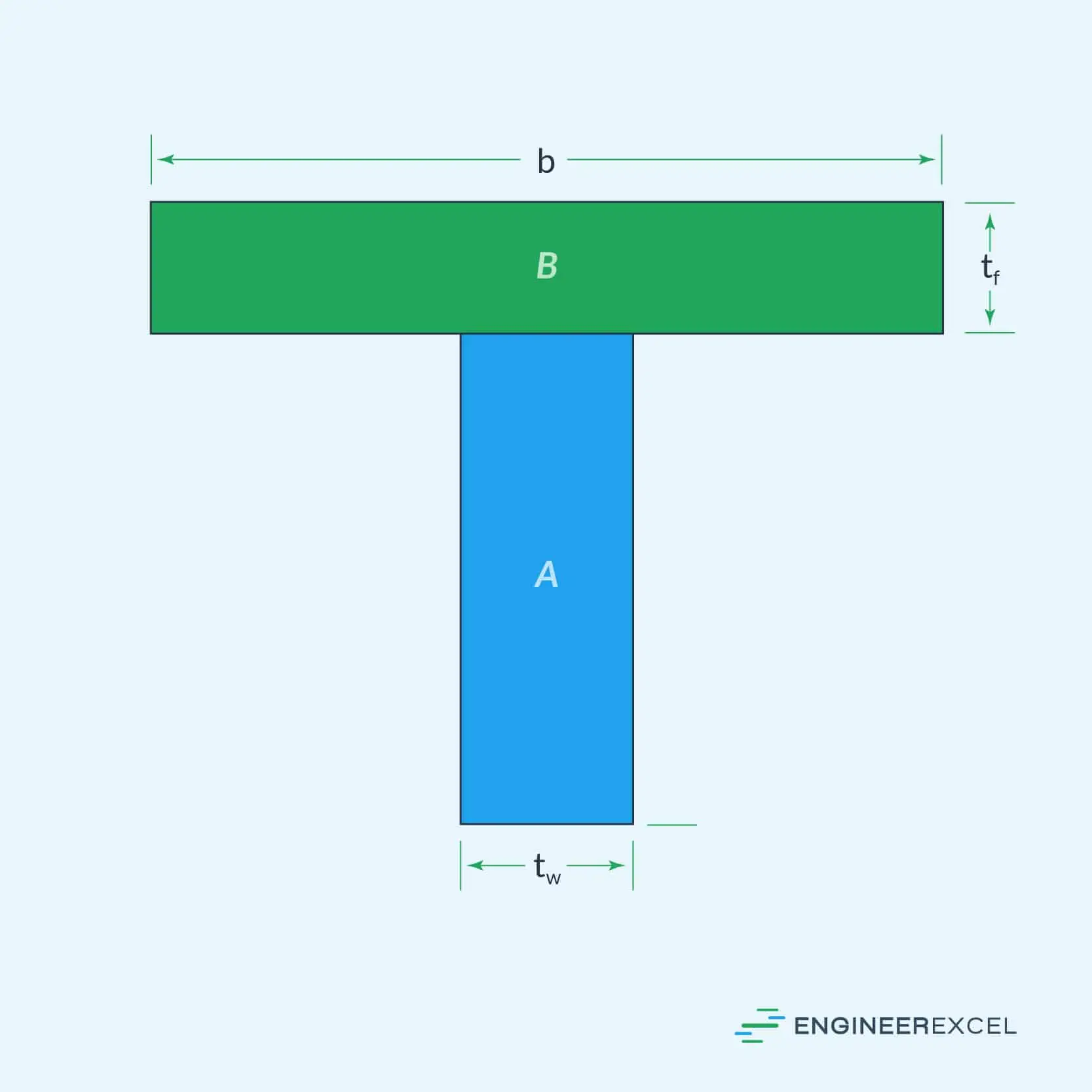
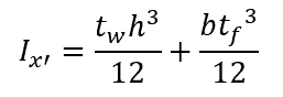
Because a T beam is not symmetric about the x-axis, it is necessary to calculate the moment of inertia about the x’-axis, and use the parallel axis theorem to determine the moment of inertia about the x-axis. The moment of inertia of a T beam about the x’-axis is calculated using the following equation:

Elevate Your Engineering With Excel
Advance in Excel with engineering-focused training that equips you with the skills to streamline projects and accelerate your career.
where:
- tw is the width of the thickness of the web, with SI units of m
- h is the height of the beam, with SI units of m
- b is the width of the flange, with SI units of m
- tf is the thickness of the flange, with SI units of m
Note that in common engineering applications, the dimensions of a T beam may be given in mm. In that case, the moment of inertia about the x’-axis, Ix’, will have SI units of mm4.
Parallel Axis Theorem
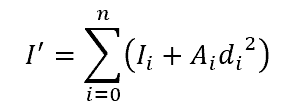
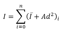
The parallel axis theorem specifies that the moment of inertia about a non-centroid axis can be calculated using the moment of inertia about a centroid axis, so long as the two axes are parallel. This theorem is simplified as follows:
where:
- I’ is the moment of inertia about the non-centroid axis, with SI units of mm4
- I is the moment of inertia about the centroid axis, with SI units of mm4
- A is the cross-sectional area beam, with SI units of mm2
- d is the distance between the two axes, with SI units of mm
Applying The Parallel Axis Theorem
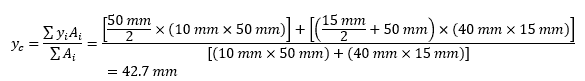
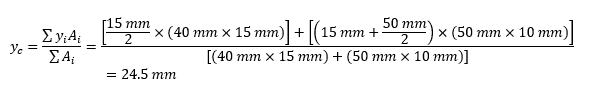
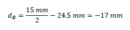
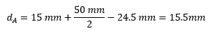
To apply the parallel axis theorem to calculate the moment of inertia of a T beam, the first step is to determine the distance between the two axes, Ix’ and Ix. In the case of a T beam, the centroidal axis is ȳc, so the distance between the two axes can be calculated with the following equation:
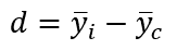
where:
- ȳi is the centroid of the i-th part of the T beam, with SI units of mm
- ȳc is the centroid of the entire beam, with SI units of mm
How To Find The Centroid Of A T Beam
To calculate the value of ȳc, the following equation is used:
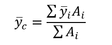
Using the above equation, the centroid of the entire beam is calculated using the individual centroids of the components that the beam was split into.
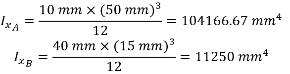
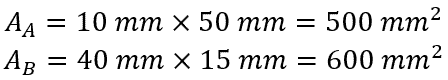
Example Calculation
To demonstrate the calculation of the moment of inertia about the x-axis for a T beam, assume a T beam with the following dimensions:
- tw = 10 mm
- h = 50 mm
- b = 40 mm
- tf = 15 mm
To calculate the moment of inertia about the x-axis, the following steps are taken:
- Calculate the moment of inertia of the two sections about their individual x-axis:
- Calculate the area of each section of the T beam:
- Calculate the location of the y-axis centroid:
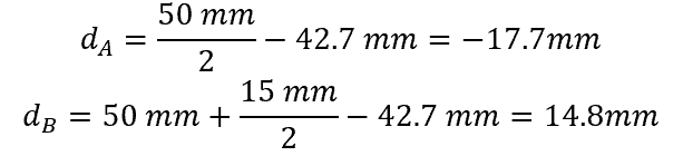
- Calculate the distance between the x-axis and the y-axis centroid for each section:
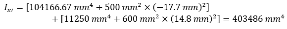
- Calculate the moment of inertia about the x-axis:
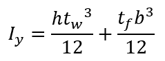
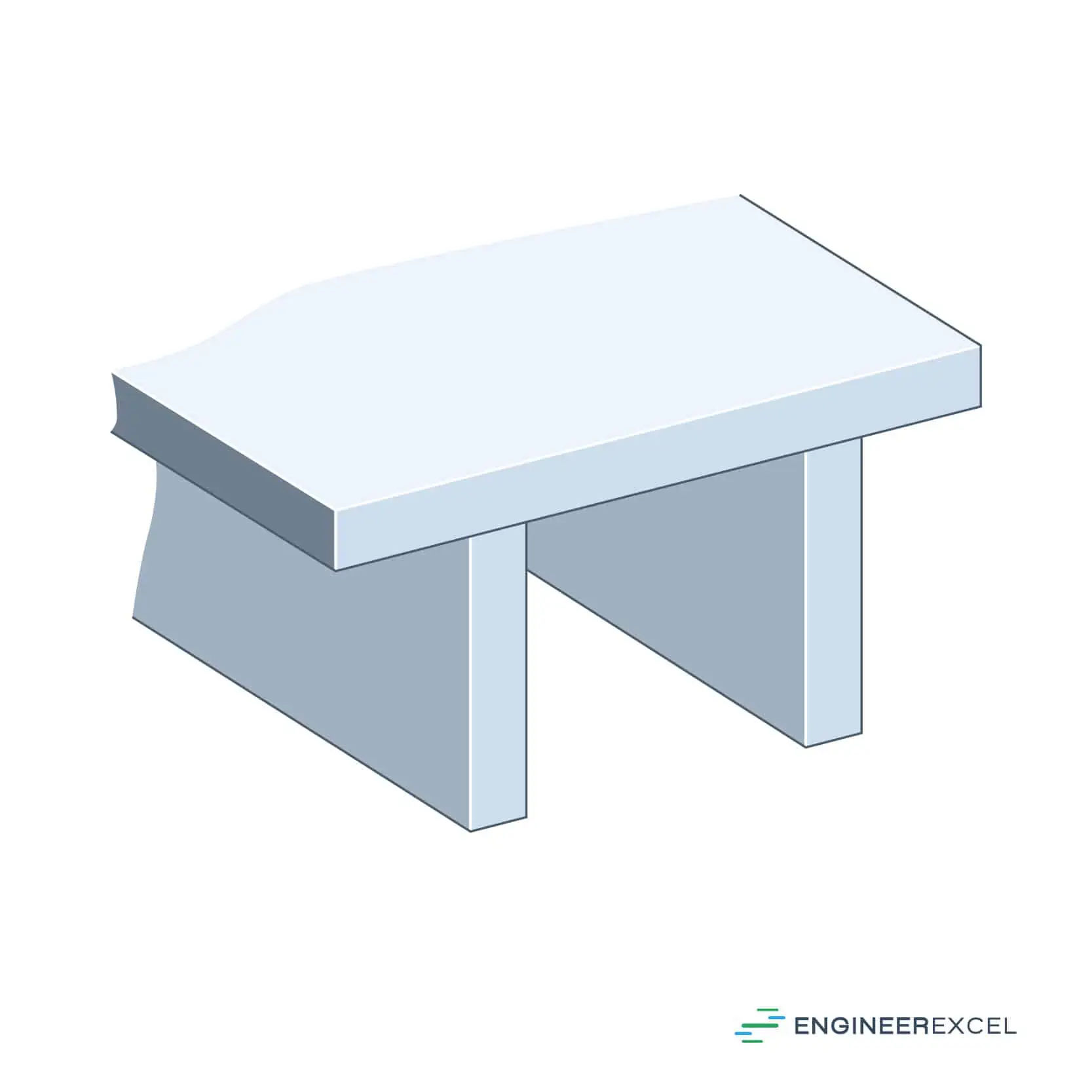
T Beam Moment Of Inertia About Y-Axis
To calculate the moment of inertia of a T beam about its y-axis, the beam must again be divided into two sections, as follows:
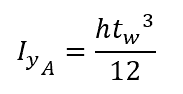
Therefore, the moment of inertia of section A is calculated as follows:
And the moment of inertia of section B is calculated as follows:
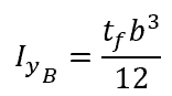
Finally, adding the two together, the total moment of inertia of the T beam is calculated as follows:
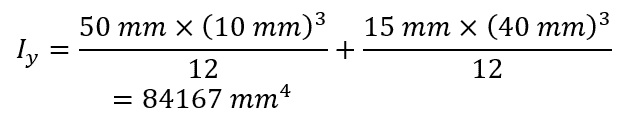
Example Calculation
Using the same T beam, the moment of inertia about the y-axis is as follows:
Extension Of T Beam Moment Of Inertia
Beginning with the moment of inertia of a T beam, there are further extensions, which are introduced below.
Double T Beam Moment Of Inertia
A double T beam is made up of three plates, as shown in the following figure:
To calculate the moment of inertia of such a beam, it is necessary to split it into two identical pieces and sum the individual moments of inertia about the centroid of the complete structure, using the following equation:
The above equation may look familiar, as it is a slight variation on the parallel axis theorem. In the case of a double T beam, n will be two, but the same concept can be applied for calculating the total moment of inertia for objects that are divided into more than two pieces, so long as the individual moment of inertia of each piece is calculated about the same centroid.
In fact, since the pieces are identical, it is only necessary to calculate the moment of inertia for one section, and then use the same numerical value and the distance from the centroid on both sides.
Inverted T Beam Moment Of Inertia
In the event that a T beam is used in an inverted orientation, the moment of inertia about the x-axis will be different than that about a traditional T beam orientation. If the same T beam as above were inverted, its moment of inertia would be calculated as follows:

Application Of The Moment Of Inertia Of A T Beam
A T beam is a common structural element used in engineering designs. Using the moments of inertia, the response of the beam to various forces can be evaluated. With an understanding of how a beam will respond to the expected forces in a specific application, it is possible to optimize the design of the beam for support, as well as mass and cost.