
In a piping system, valves are used to control the flow rate by adjusting the size of the flow passage or by changing the resistance within the passage; however, this operation inevitably leads to pressure loss. In fluid mechanics, this pressure loss caused by valves is quantified through loss coefficients.

This article specifically tackles the loss coefficient of the needle valve— a type of valve designed for precise flow control.
Needle Valve Loss Coefficients
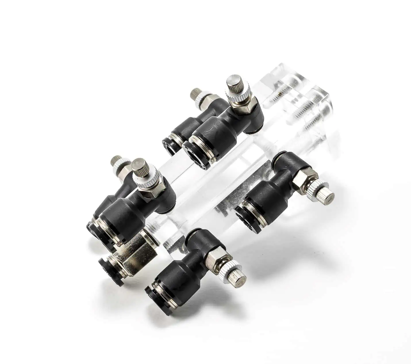
Before getting into the loss coefficient of needle valves, it is important to first understand what a needle valve is and how it operates.
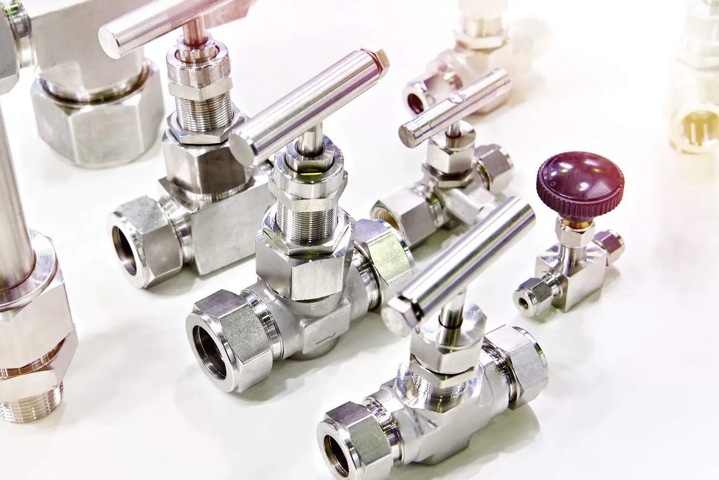
A needle valve is a type of flow control valve intended for fine and precise control in relatively low flow rate applications. Its name is derived from its distinctive flow control element, characterized by a long-taper, slender, and pointed plug that resembles a needle. The position of this needle-like element can be adjusted to vary the size of the opening and regulate flow as it plunges into the valve seat, which is why they are also referred to as plunger valves.

Elevate Your Engineering With Excel
Advance in Excel with engineering-focused training that equips you with the skills to streamline projects and accelerate your career.
The following diagram illustrates a needle valve and its schematic symbol.
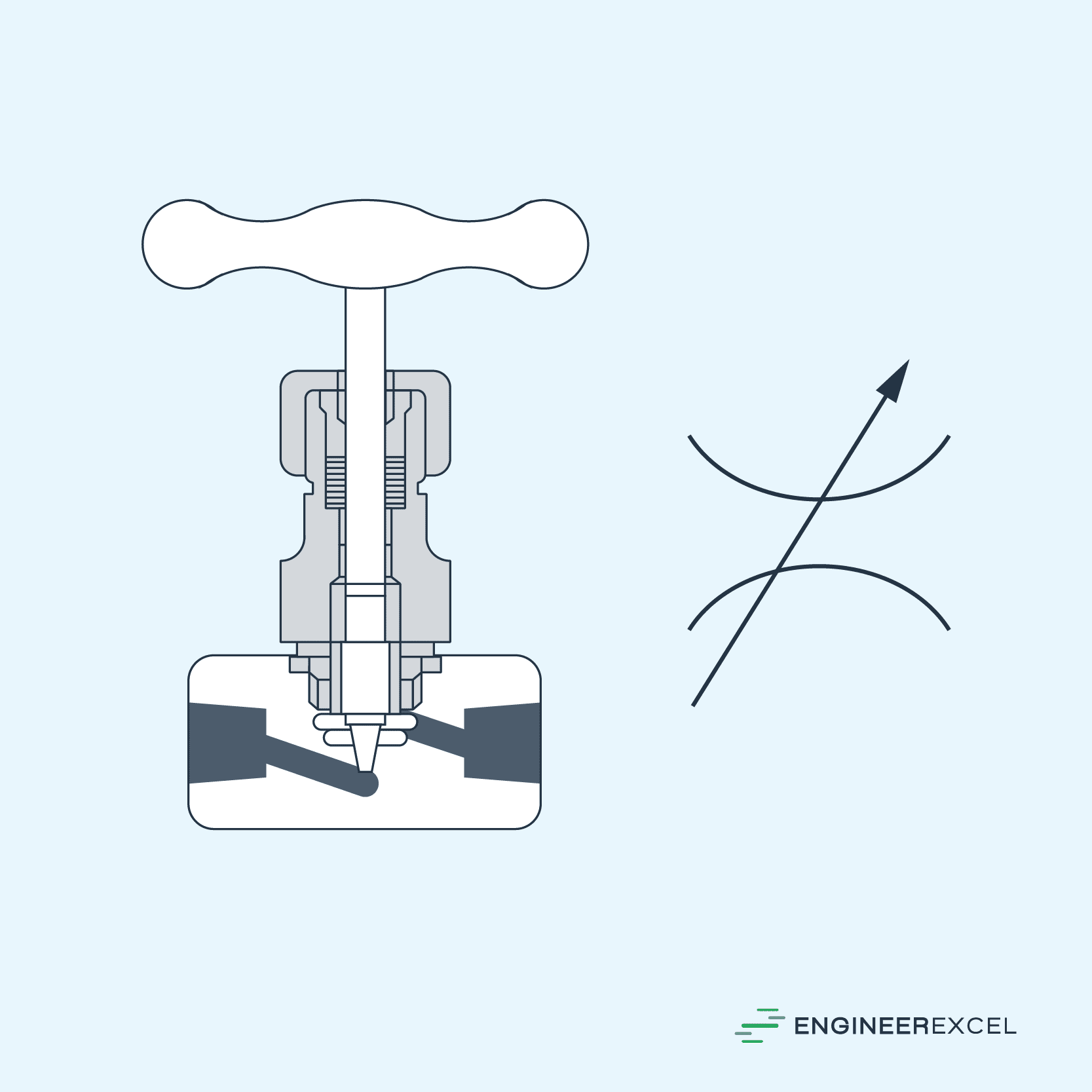
The precision of the needle valve is achieved through the vernier effect of the ratio between the needle’s length and its diameter. This means that it requires numerous rotations of the finely threaded screw to retract the plunger, enabling precise control of the flow rate.
However, needle valves, much like any other valve, inherently create resistance within a fluid flow. This resistance, in turn, results in a drop in pressure or head loss. In piping systems, these head losses attributed to valves are commonly referred to as minor losses.
Minor losses are quantified using dimensionless parameters called loss coefficients. These coefficients measure the ratio between the head loss incurred due to the insertion of the valve and the kinetic energy of the flow, as shown in the following equation:
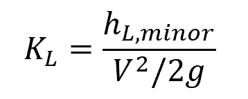
Where:
- KL = loss coefficient of the needle valve [unitless]
- hL, minor = head loss caused by the needle valve [m]
- V = average fluid velocity [m/s]
- g = gravitational acceleration [9.81 m/s2]
Loss coefficients are usually determined through experimental testing and then correlated with pipe flow parameters. Because of the variations in valve configurations and material compositions, needle valves can have different loss coefficient values among different manufacturers. Hence, these values are normally provided by manufacturers.
Needle valve bodies can be constructed from various materials such as brass, bronze, stainless steel, or other alloys, while valve seats are typically made from thermoplastics like PVC, CPVC, or PTFE.
Needle valves generally share many similarities with globe valves, except for their size and valve trim geometry. In fact, the pressure and temperature limits of needle valves closely align with those of globe valves. The same is true for their loss coefficients; when fully open, needle valves tend to exhibit similar loss coefficients to globe valves.
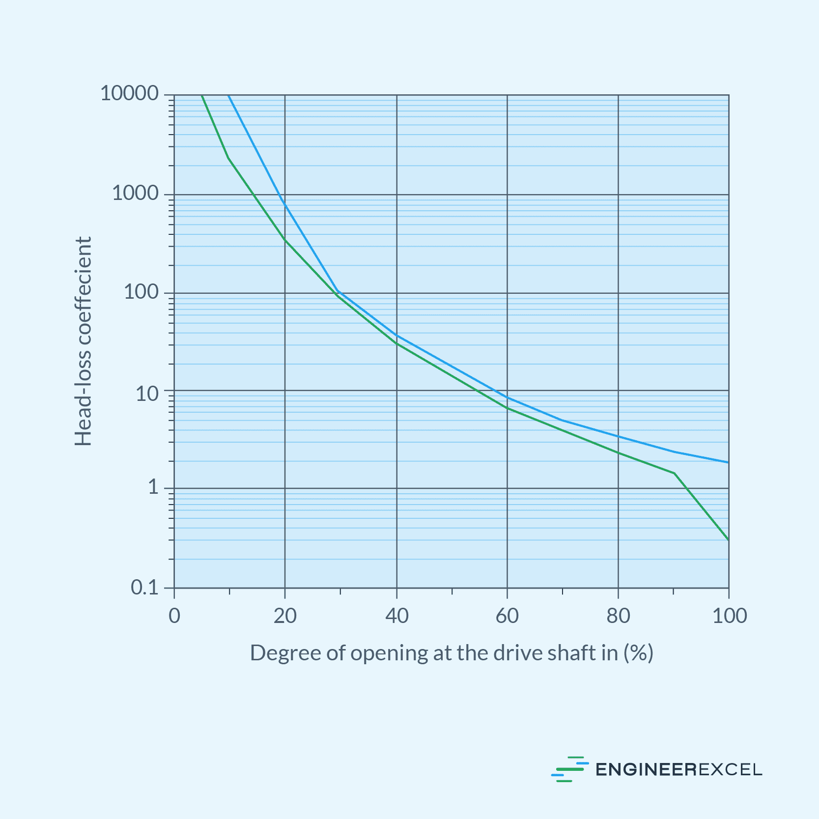
The graph below illustrates how the loss coefficient behaves in relation to the degree of opening for a representative needle valve. One curve represents the DN300 size, while the other curve represents sizes DN350-1400.
Coefficient of Flow (Cv) for Needle Valves
Aside from the loss coefficient, another commonly used parameter for characterizing the pressure drop across a needle valve is the capacity coefficient, also known as the coefficient of flow. While the loss coefficient associates head loss with fluid velocity, the coefficient of flow relates pressure drop to the fluid’s volumetric flow rate. This relationship is shown by the following equation:
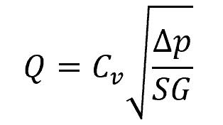
Where:
- Q = volumetric flow rate [Lpm]
- Cv = coefficient of flow of the needle valve [Lpm/ kPa1/2]
- Δp = pressure drop across the needle valve [kPa]
- SG = specific gravity of the fluid [unitless]
In metric units, the coefficient of flow is defined as the flow rate of water across the valve in liters per minute at a pressure drop of 1 kPa. Like the loss coefficient, the coefficient of flow is determined experimentally in the fully open position and is listed as the “rated Cv” in manufacturers’ catalogs.
Applications of Needle Valves
Due to the restricted flow passage between the needle and valve seat, needle valves are usually limited to applications with low flow rates and small-diameter pipes, typically up to 2 inches in size. They are ideal for applications that require precise and gradual flow adjustments, particularly in continuous throttling, such as in laboratory experiments, instrumentation, and sample points within piping systems.
Needle valves work well with a variety of fluids, including steam, air, gas, oil, water, and other non-viscous liquids. They serve various purposes across different industries.
In irrigation and production systems, for example, they can be used for chemical injection. In vacuum systems, they can be used when filling gas-filled vacuum tubes and gas lasers. In water-heating systems, they can be used as bleed valves.
In general, needle valves are easy to completely shut off due to their small orifice and the high force advantage provided by the fine-threaded stem, requiring only a ‘finger-tight’ pressure.