
Axial deformation refers to the change in length of a material along its longitudinal axis under applied force or load. It typically occurs in structures such as beams, columns, or rods, where the material experiences compression or tension forces along its length, resulting in either elongation or contraction. In this article, we will delve into the causes of axial deformation, the stress-strain relationship for materials under axial deformation, and the various techniques used to measure axial deformation in engineering applications.
What is Axial Deformation
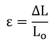
Axial deformation refers to the change in length of an engineering component along its longitudinal axis. This phenomenon occurs when an axial force is applied to a member, causing it to either stretch or shorten. Axial deformation can be quantified as the change in length over the original length, commonly expressed as:
Where:
- ε = axial deformation [unitless]
- ΔL = change in length of the component [m]
- L₀ = original length of the component [m]

Elevate Your Engineering With Excel
Advance in Excel with engineering-focused training that equips you with the skills to streamline projects and accelerate your career.
The deformation is considered positive when the length of the component increases, indicating elongation, and negative when the length of the component decreases, indicating compression.
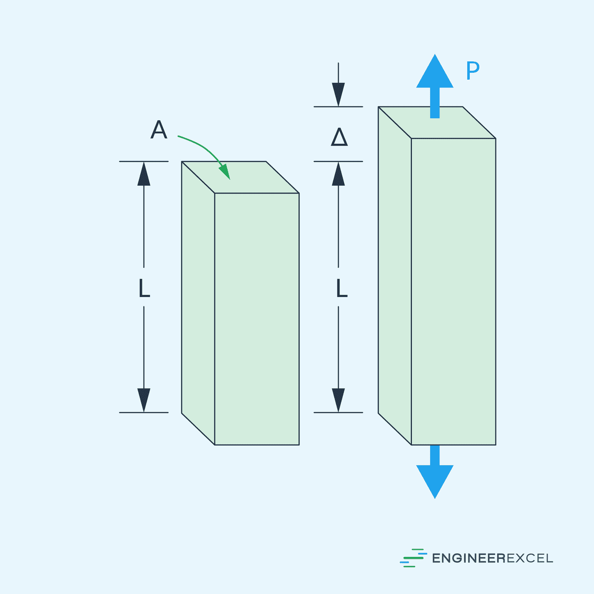
Unlike shear or torsional deformation, axial deformation does not involve any change in the shape of cross sections perpendicular to the axis of the member. During axial deformation, the cross sections are assumed to remain flat and perpendicular to the longitudinal axis, without any rotation about the axis.
While axial, shear, and torsional deformations can all occur simultaneously in real-world applications, each type of deformation is often analyzed separately to simplify complex problems. This assumption holds true particularly in structures where the member experiences primarily uniaxial stresses and the effects of other stress types are minimal in comparison.
Causes of Axial Deformation
Axial deformation can be the result of various factors, each posing unique challenges to the integrity of materials and structures.
Tensile Loads
When a material is subject to tensile loads, it experiences forces that try to elongate it. The axial deformation in this case is characterized by stretching the material.
Compressive Loads
Contrary to tensile loads, compressive loads press the material together, causing it to shorten along the axis. The degree of deformation depends on the material’s compressive strength and the magnitude of the applied load.
Temperature Changes
Temperature changes can lead to thermal expansion or contraction of a material. Expansion occurs when the temperature rises, while contraction happens as temperatures fall. The degree of axial deformation is a function of the material’s thermal expansion coefficient and the temperature change it undergoes.
Material Defects
Material defects, such as inclusions, micro-cracks, or voids, can reduce the load-bearing capacity and result in non-uniform axial deformation. The presence of imperfections often leads to localized areas of stress concentration which may intensify deformation under load.
Stress-Strain Relationship in Axial Deformation
When a material is subjected to an axial force, it experiences a change in length, which is referred to as strain, while the internal resistance to deformation is known as stress. The relationship between stress (σ) and strain (ε) is often depicted graphically as a curve on a stress-strain diagram and can be mathematically described by various models, depending on whether the material is ductile or brittle.
Axial Deformation of Ductile Materials
The typical stress-strain curve for a ductile material is shown in the diagram below.
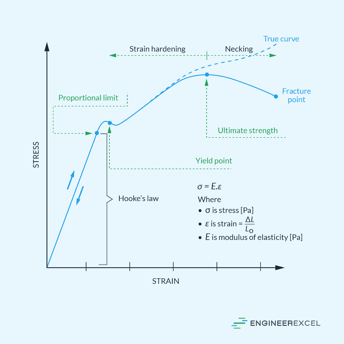
In the initial portion of the curve, the material deforms elastically, which means that it returns to its original shape once the load is removed. The relationship between stress and strain in this region is linear and is defined by Hooke’s Law, which can be expressed as:
Where:
- σ = stress [Pa]
- E = Young’s modulus [Pa]
- ε = strain [unitless]
The proportional limit marks the point up to which stress is directly proportional to strain and Hooke’s Law is valid. Close to this point are the elastic limit and the yield point of the material.
The elastic limit represents the maximum stress that a material can endure while still being able to return to its original shape upon unloading. In contrast, the yield point is where the material begins to deform plastically.
Beyond this point, the material will not return to its original shape even if the load is removed, resulting in permanent deformation in the plastic region. In this region, the relationship between stress and strain becomes nonlinear. Some materials exhibit strain hardening, where the stress required to continue deforming the material increases with strain.
The ultimate strength is the maximum stress that the material can withstand before experiencing necking, which is a local reduction in cross-sectional area. Finally, the fracture point is where the material ultimately fails and breaks.
Axial Deformation of Brittle Materials
The stress-strain curve for brittle materials differs from that of ductile materials. Brittle materials typically lack a distinct yield point and do not undergo significant plastic deformation before fracture. Although they also have a linear elastic region following Hooke’s Law, this region is typically very steep, indicating a high modulus of elasticity.

For brittle materials, the elastic limit is often considered the point at which the material will fracture, with the stress at fracture representing the ultimate tensile strength of the material. Fracture in brittle materials occurs suddenly after reaching the ultimate tensile strength, with little to no plastic deformation and minimal warning after surpassing the elastic limit.
Measurement of Axial Deformation
Strain Gauges
Strain gauges are tools used for determining axial deformation. They work by converting mechanical deformation into an electrical signal.
A typical strain gauge setup involves a thin foil pattern attached to a flexible backing connected to a Wheatstone bridge circuit. Strain is then calculated by measuring the change in electrical resistance as the material deforms.
Optical Methods
Optical methods include several techniques like photoelasticity and laser interferometry that provide non-contact means of measuring deformation. They rely on analyzing changes in light properties as it interacts with the deformed material. For instance, in photoelasticity, patterns of light and dark fringes correlate to stress distribution and deformation.
Acoustic Emission Technique
The acoustic emission technique detects stress waves emitted from a material as it undergoes deformation. Microphones or transducers placed on the surface of the material capture these waves. This method is advantageous for acquiring a real-time and continuous monitoring capability, particularly useful in detecting the onset of material failure.
Laser Scanning
Laser scanning, such as 3D laser triangulation, delivers high-resolution topographic measurements of the material’s surface. The technology is highly precise and can measure both large and minute deformations. A laser scanner projects a beam onto the surface while sensors capture the reflection to determine deformation profiles with notable accuracy.