
When it comes to monitoring fluid flow in pipelines, precision is important in order to ensure efficient, safe, and compliant system operation. One important factor to consider when installing a flow metering instrument is its location within the system.
This article tackles the critical aspects of flow meter placement in order to achieve accurate flow monitoring.
Where Should A Flow Meter Be Placed
Before delving into the proper placement and installation of flowmeters, it is important to begin by defining flow meters and exploring their various types.
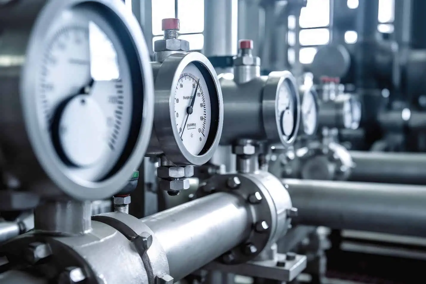
A flow meter is a device used to measure the flow rate of a fluid, such as liquid or gas, in a pipe or conduit. There are many types of flow meters. They range widely in their level of sophistication, size, cost, accuracy, versatility, capacity, pressure drop, and operating principle.

Elevate Your Engineering With Excel
Advance in Excel with engineering-focused training that equips you with the skills to streamline projects and accelerate your career.
In general, they can be classified into the following functional groups: obstruction flow meters, velocity flow meters, positive displacement flow meters, open channel flow meters, and mass flow meters.
Obstruction or differential pressure flow meters measure volumetric flow rate by creating a restriction in the flow path of the fluid and calculating the flow rate based on the pressure drop across the obstruction. These include orifice plates, venturi tubes, nozzles, and pitot tubes.
Velocity flow meters measure the volumetric flow rate of a fluid by measuring its velocity in a known cross-sectional area. These include turbine, vortex, electromagnetic, and ultrasonic flowmeters.
Positive displacement flow meters measure the volumetric flow rate of a fluid by dividing it into fixed, metered volumes and counting the number of volumes that pass through the meter. These include piston, gear, nutating disc, and rotary vane flowmeters.
Open channel flow meters are devices that measure the flow rate of liquids that are open to the atmosphere, such as in trenches, rivers, or culverts. These meters calculate the flow rate by measuring the fluid level and the cross-sectional area of the channel. Some common types of open channel flow meters are flumes, weirs, and ultrasonic level sensors.
Mass flow meters are devices that measure the mass flow rate of a fluid traveling through a conduit, rather than the volumetric flow rate. Some common types of mass flow meters are thermal and Coriolis flowmeters. Thermal mass flow meters measure the mass flow rate of a fluid by measuring the heat transfer from a heated surface to the flowing fluid, while Coriolis mass flow meters measure the deflection of a vibrating tube caused by the Coriolis force acting on the fluid.
Since there are several types of flow meters operating using different principles, determining the ideal location for a flow meter within a pipeline is not a one-size-fits-all solution. The choice of placement depends on several factors, including the type of flowmeter, the type of fluid being transported, the characteristics of the conduit, and the specific goals of the monitoring system. However, there are general guidelines that need to be observed when installing flowmeters:
Avoid Placing The Flow Meter After A Valve Or Any Obstruction
To obtain accurate flow measurements, flowmeters are typically installed in locations where the flow is steady, full, and well-defined, such as upstream of valves, pumps, or other components that can influence flow. This ensures that the flowmeter measures the true flow rate without interference from flow restrictions or pressure changes introduced by valves.
Place The Flowmeter Concentric With The Pipe
The flowmeter is typically placed concentric with the pipe so that it detects a reliable representative sample of the fluid’s velocity profile. When a flowmeter is installed off-center, it can create disturbances in the fluid flow, which leads to variations in velocity and pressure profiles across the pipe cross-section. These disturbances can cause inaccuracies in flow measurement.
A concentric installation also minimizes the pressure drop across the flowmeter. When a flowmeter is placed off-center, it can create additional resistance to the flow of fluid, leading to an increase in pressure drop. This can affect the efficiency of the system and potentially cause damage to equipment downstream.
Place The Flowmeter Away From Electromagnetic Fields
Fluid flow can be affected by strong electromagnetic fields through a phenomenon known as magnetohydrodynamics (MHD). This is true for electrically conducting fluids, such as plasmas, ionized gases, and some liquid metals.
Furthermore, electromagnetic fields can interfere with the functioning of electronic equipment, including flowmeters. When a flowmeter is exposed to strong electromagnetic fields, it may produce inaccurate readings or fail to operate altogether.
Provide Clearance For Installation And Maintenance
Flowmeters are often installed in industrial or process environments where hazardous materials or conditions may exist. Providing adequate clearance ensures that personnel can safely access the flowmeter for installation, inspection, and maintenance without exposing themselves to risks. This includes ensuring there is enough space for tools and equipment necessary for maintenance tasks.
Avoid Placing Flowmeter Near Inlet And Outlet Piping
Placing a flow meter too close to the inlet or outlet of a pipeline can lead to inaccuracies in measurement due to turbulence and irregular flow patterns near these points. To mitigate this, it is generally advisable to install a sufficient length of straight pipe before and after the flow meter.
Insert Between Two Sections Of Straight Pipe Of Constant Area
As mentioned above, the flowmeter should be placed between two sections of straight pipe of constant cross-sectional area, without any obstruction or branch connection. This is because irregular flow patterns can occur near obstructions or branches in the pipe, which can lead to inaccuracies in flow measurement.
This straight run provides a stable flow profile, allowing the flow meter to obtain consistent and accurate readings. The required minimum straight lengths of pipe depend on the nature of fittings, the type of flowmeter, and the diameter ratio.
The diameter ratio is the ratio of the diameter of the obstruction to the diameter of the pipe, such that:
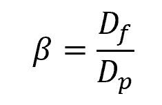
Where:
- β = diameter ratio [unitless]
- Df = diameter of the obstruction [mm or in]
- Dp = diameter of the pipe [mm or in]
Use Flow Conditioners
If placement near obstructions is unavoidable, consider installing a flow conditioning device in the upstream straight length between the flowmeter and the obstruction or fitting closest to the flowmeter.
Flow conditioners are devices used in pipelines to improve the flow characteristics of a fluid, especially in situations where the flow profile is non-uniform or turbulent. They are designed to ensure that the fluid entering a flowmeter, has a stable and predictable flow profile, which is essential for accurate and reliable flow measurements.
There are different types of flow conditioners, including Zanker conditioner, Sprenkle conditioner, tube bundle conditioner, AMCA straightener, and Etolle straightener. Choosing which conditioner to use depends on the nature of the velocity distribution and the amount of additional pressure loss that can be tolerated.
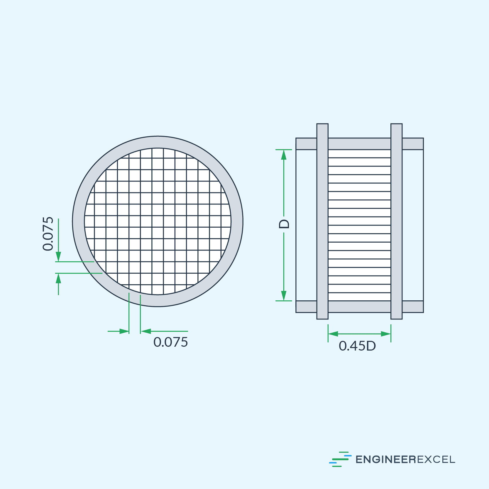
To give a sample illustration, a diagram of the AMCA straightener is shown below.
Flow Meter Installation Standards
There are different standards used for flowmeter installation depending on the type of flowmeter, the fluid being measured, and the application.
For example, ISO 5167 and ASME MFC-3M are used for pressure differential flowmeters, like orifice plates, nozzles, and Venturi tubes, inserted in circular cross-section conduits running full. ASME MFC-11 is used for the measurement of fluid flow by means of Coriolis mass flowmeters. Lastly, ISO 20456 is used for the measurement of fluid flow in closed conduits using electromagnetic flowmeters for conductive fluids.
In general, however, it is important to follow the specific guidelines provided by the flowmeter manufacturer, in addition to industry standards. These guidelines are tailored to the particular flowmeter model and offer more accurate insights into proper installation and maintenance of the product.