
[no_toc]
W-beams are a type of structural steel members used in the construction industry. Also known as wide-flange beams, these beams have a wide flange profile on either side of the web. W-beams are characterized by their depth, unit weight, flange width, web thickness, and flange thickness.
W-Beam Dimensions
| Designation | Depth [in] | Width [in] | Area [in^2] | Weight [lb/ft] | t, Web [in] | t,Flange [in] | Ix [in^4] | Sx [in^4] |
|---|---|---|---|---|---|---|---|---|
| W4x13 | 4.16 | 4.06 | 3.8 | 13 | 0.28 | 0.35 | 11.2 | 5 |
| W5x16 | 5.01 | 5 | 4.7 | 16 | 0.24 | 0.36 | 21.1 | 8 |
| W5x19 | 5.15 | 5.03 | 5.5 | 19 | 0.27 | 0.43 | 25.9 | 10 |
| W6x9 | 5.9 | 3.94 | 2.7 | 9 | 0.17 | 0.22 | 16 | 5 |
| W6x12 | 6.03 | 4 | 3.6 | 12 | 0.23 | 0.28 | 21.7 | 7 |
| W6x15 | 5.99 | 5.99 | 4.4 | 15 | 0.23 | 0.26 | 28.7 | 10 |
| W6x16 | 6.28 | 4.03 | 4.7 | 16 | 0.26 | 0.41 | 31.8 | 10 |
| W6x20 | 6.2 | 6.02 | 5.9 | 20 | 0.26 | 0.37 | 41 | 13 |
| W6x25 | 6.38 | 6.08 | 7.3 | 25 | 0.32 | 0.46 | 53 | 17 |
| W8x10 | 7.89 | 3.94 | 2.9 | 10 | 0.17 | 0.21 | 29.8 | 8 |
| W8x13 | 7.99 | 4 | 3.8 | 13 | 0.23 | 0.26 | 38.5 | 10 |
| W8x15 | 8.11 | 4.02 | 4.4 | 15 | 0.25 | 0.32 | 47 | 12 |
| W8x18 | 8.14 | 5.25 | 5.3 | 18 | 0.23 | 0.33 | 60.9 | 15 |
| W8x21 | 8.28 | 5.27 | 6.2 | 21 | 0.25 | 0.4 | 74.2 | 18 |
| W8x24 | 7.93 | 6.5 | 7.1 | 24 | 0.25 | 0.4 | 81.1 | 20 |
| W8x28 | 8.06 | 6.54 | 8.3 | 28 | 0.29 | 0.47 | 96.4 | 24 |
| W8x31 | 8 | 8 | 9.1 | 31 | 0.29 | 0.44 | 108 | 27 |
| W8x35 | 8.12 | 8.02 | 10.3 | 35 | 0.31 | 0.5 | 125 | 31 |
| W8x40 | 8.25 | 8.07 | 11.7 | 40 | 0.36 | 0.56 | 145 | 35 |
| W8x48 | 8.5 | 8.11 | 14.1 | 48 | 0.4 | 0.69 | 182 | 43 |
| W8x58 | 8.75 | 8.22 | 17.1 | 58 | 0.51 | 0.81 | 226 | 52 |
| W8x67 | 9 | 8.28 | 19.7 | 67 | 0.57 | 0.94 | 270 | 60 |
| W10x12 | 9.87 | 3.96 | 3.5 | 12 | 0.19 | 0.21 | 52.2 | 11 |
| W10x15 | 9.99 | 4 | 4.4 | 15 | 0.23 | 0.27 | 67.2 | 13 |
| W10x17 | 10.11 | 4.01 | 5 | 17 | 0.24 | 0.33 | 80.2 | 16 |
| W10x19 | 10.24 | 4.02 | 5.6 | 19 | 0.25 | 0.4 | 94.6 | 18 |
| W10x22 | 10.17 | 5.75 | 6.5 | 22 | 0.24 | 0.36 | 117 | 23 |
| W10x26 | 10.33 | 5.77 | 7.6 | 26 | 0.26 | 0.44 | 143 | 28 |
| W10x30 | 10.47 | 5.81 | 8.8 | 30 | 0.3 | 0.51 | 168 | 32 |
| W10x33 | 9.73 | 7.96 | 9.7 | 33 | 0.29 | 0.44 | 166 | 34 |
| W10x39 | 9.92 | 7.99 | 11.5 | 39 | 0.32 | 0.53 | 205 | 41 |
| W10x45 | 10.1 | 8.02 | 13.3 | 45 | 0.35 | 0.62 | 244 | 48 |
| W10x49 | 9.98 | 10 | 14.4 | 49 | 0.34 | 0.56 | 268 | 54 |
| W10x54 | 10.09 | 10.03 | 15.8 | 54 | 0.37 | 0.62 | 299 | 59 |
| W10x60 | 10.22 | 10.08 | 17.6 | 60 | 0.42 | 0.68 | 337 | 66 |
| W10x68 | 10.4 | 10.13 | 20 | 68 | 0.47 | 0.77 | 390 | 75 |
| W10x77 | 10.6 | 10.19 | 22.6 | 77 | 0.53 | 0.87 | 451 | 85 |
| W10x88 | 10.84 | 10.27 | 25.9 | 88 | 0.61 | 0.99 | 530 | 98 |
| W10x100 | 11.1 | 10.34 | 29.4 | 100 | 0.68 | 1.11 | 616 | 111 |
| W10x112 | 11.36 | 10.42 | 32.9 | 112 | 0.76 | 1.25 | 712 | 125 |
| W12x14 | 11.91 | 3.97 | 4.2 | 14 | 0.2 | 0.23 | 86.1 | 14 |
| W12x16 | 11.99 | 3.99 | 4.7 | 16 | 0.22 | 0.27 | 100 | 17 |
| W12x19 | 12.16 | 4.01 | 5.6 | 19 | 0.24 | 0.35 | 127 | 21 |
| W12x22 | 12.31 | 4.03 | 6.5 | 22 | 0.26 | 0.43 | 154 | 25 |
| W12x26 | 12.22 | 6.49 | 7.7 | 26 | 0.23 | 0.38 | 202 | 33 |
| W12x30 | 12.34 | 6.52 | 8.8 | 30 | 0.26 | 0.44 | 236 | 38 |
| W12x35 | 12.5 | 6.56 | 10.3 | 35 | 0.3 | 0.52 | 283 | 45 |
| W12x40 | 11.94 | 8.01 | 11.8 | 40 | 0.3 | 0.52 | 301 | 50 |
| W12x45 | 12.06 | 8.05 | 13.2 | 45 | 0.34 | 0.58 | 342 | 57 |
| W12x50 | 12.19 | 8.08 | 14.7 | 50 | 0.37 | 0.64 | 385 | 63 |
| W12x53 | 12.06 | 10 | 15.6 | 53 | 0.35 | 0.58 | 417 | 69 |
| W12x58 | 12.19 | 10.01 | 17 | 58 | 0.36 | 0.64 | 467 | 77 |
| W12x65 | 12.12 | 12 | 19.1 | 65 | 0.39 | 0.61 | 524 | 86 |
| W12x72 | 12.25 | 12.04 | 21.1 | 72 | 0.43 | 0.67 | 588 | 96 |
| W12x79 | 12.38 | 12.08 | 23.2 | 79 | 0.47 | 0.74 | 654 | 106 |
| W12x87 | 12.53 | 12.13 | 25.6 | 87 | 0.52 | 0.81 | 731 | 117 |
| W12x96 | 12.71 | 12.16 | 28.2 | 96 | 0.55 | 0.9 | 824 | 130 |
| W12x106 | 12.89 | 12.22 | 31.2 | 106 | 0.61 | 0.99 | 925 | 143 |
| W12x120 | 13.12 | 12.32 | 35.3 | 120 | 0.71 | 1.11 | 1062 | 162 |
| W12x136 | 13.41 | 12.4 | 39.9 | 136 | 0.79 | 1.25 | 1235 | 184 |
| W14x22 | 13.74 | 5 | 6.5 | 22 | 0.23 | 0.34 | 193 | 28 |
| W14x26 | 13.91 | 5.03 | 7.7 | 26 | 0.26 | 0.42 | 240 | 34 |
| W14x30 | 13.84 | 6.73 | 8.9 | 30 | 0.27 | 0.39 | 285 | 41 |
| W14x34 | 13.98 | 6.75 | 10 | 34 | 0.29 | 0.46 | 334 | 48 |
| W14x38 | 14.1 | 6.77 | 11.2 | 38 | 0.31 | 0.52 | 380 | 54 |
| W14x43 | 13.66 | 8 | 12.6 | 43 | 0.31 | 0.53 | 416 | 61 |
| W14x48 | 13.79 | 8.03 | 14.1 | 48 | 0.34 | 0.6 | 473 | 69 |
| W14x53 | 13.92 | 8.06 | 15.6 | 53 | 0.37 | 0.66 | 530 | 76 |
| W14x61 | 13.89 | 10 | 17.9 | 61 | 0.38 | 0.65 | 628 | 90 |
| W14x68 | 14.04 | 10.04 | 20 | 68 | 0.42 | 0.72 | 711 | 101 |
| W14x74 | 14.17 | 10.07 | 21.8 | 74 | 0.45 | 0.79 | 784 | 111 |
| W14x82 | 14.31 | 10.13 | 24.1 | 82 | 0.51 | 0.86 | 870 | 122 |
| W14x90 | 14.02 | 14.52 | 26.5 | 90 | 0.44 | 0.71 | 987 | 141 |
| W14x99 | 14.16 | 14.57 | 29.1 | 99 | 0.49 | 0.78 | 1099 | 155 |
| W14x109 | 14.32 | 14.61 | 32 | 109 | 0.53 | 0.86 | 1227 | 171 |
| W14x120 | 14.48 | 14.67 | 35.3 | 120 | 0.59 | 0.94 | 1364 | 188 |
| W14x132 | 14.66 | 14.73 | 38.8 | 132 | 0.65 | 1.03 | 1519 | 207 |
| W16x26 | 15.69 | 5.5 | 7.7 | 26 | 0.25 | 0.35 | 294 | 37 |
| W16x31 | 15.88 | 5.53 | 9.1 | 31 | 0.28 | 0.44 | 367 | 46 |
| W16x36 | 15.86 | 6.99 | 10.6 | 36 | 0.3 | 0.43 | 441 | 56 |
| W16x40 | 16.01 | 7 | 11.8 | 40 | 0.31 | 0.51 | 511 | 64 |
| W16x45 | 16.13 | 7.04 | 13.3 | 45 | 0.35 | 0.57 | 579 | 72 |
| W16x50 | 16.26 | 7.07 | 14.7 | 50 | 0.38 | 0.63 | 651 | 80 |
| W16x57 | 16.43 | 7.12 | 16.8 | 57 | 0.43 | 0.72 | 750 | 91 |
| W16x67 | 16.33 | 10.24 | 19.7 | 67 | 0.4 | 0.67 | 947 | 116 |
| W16x77 | 16.52 | 10.3 | 22.6 | 77 | 0.46 | 0.76 | 1100 | 133 |
| W16x89 | 16.75 | 10.37 | 26.2 | 89 | 0.53 | 0.88 | 1292 | 154 |
| W16x100 | 16.97 | 10.43 | 29.4 | 100 | 0.59 | 0.99 | 1478 | 174 |
| W18x35 | 17.7 | 6 | 10.3 | 35 | 0.3 | 0.43 | 500 | 57 |
| W18x40 | 17.9 | 6.02 | 11.8 | 40 | 0.32 | 0.53 | 603 | 67 |
| W18x46 | 18.1 | 6.06 | 13.5 | 46 | 0.36 | 0.61 | 706 | 78 |
| W18x50 | 18 | 7.5 | 14.7 | 50 | 0.36 | 0.57 | 791 | 88 |
| W18x55 | 18.1 | 7.53 | 16.2 | 55 | 0.39 | 0.63 | 879 | 97 |
| W18x60 | 18.2 | 7.56 | 17.6 | 60 | 0.42 | 0.7 | 970 | 107 |
| W18x65 | 18.4 | 7.59 | 19.1 | 65 | 0.45 | 0.75 | 1068 | 116 |
| W18x71 | 18.5 | 7.64 | 20.8 | 71 | 0.5 | 0.81 | 1167 | 126 |
| W18x76 | 18.2 | 11.04 | 22.3 | 76 | 0.43 | 0.68 | 1322 | 145 |
| W18x86 | 18.4 | 11.09 | 25.3 | 86 | 0.48 | 0.77 | 1520 | 165 |
| W18x97 | 18.6 | 11.15 | 28.5 | 97 | 0.54 | 0.87 | 1740 | 187 |
| W18x106 | 18.7 | 11.2 | 31.1 | 106 | 0.59 | 0.94 | 1896 | 203 |
| W18x119 | 19 | 11.27 | 35.1 | 119 | 0.66 | 1.06 | 2187 | 230 |
| W21x44 | 20.7 | 6.5 | 13 | 44 | 0.35 | 0.45 | 826 | 80 |
| W21x50 | 20.8 | 6.53 | 14.7 | 50 | 0.38 | 0.54 | 961 | 92 |
| W21x57 | 21.1 | 6.56 | 16.7 | 57 | 0.41 | 0.65 | 1154 | 109 |
| W21x62 | 21 | 8.24 | 18.3 | 62 | 0.4 | 0.62 | 1311 | 125 |
| W21x68 | 21.1 | 8.27 | 20 | 68 | 0.43 | 0.69 | 1456 | 138 |
| W21x73 | 21.2 | 8.3 | 21.5 | 73 | 0.46 | 0.74 | 1577 | 149 |
| W21x83 | 21.4 | 8.36 | 24.3 | 83 | 0.52 | 0.84 | 1807 | 169 |
| W21x93 | 21.6 | 8.42 | 27.3 | 93 | 0.58 | 0.93 | 2046 | 189 |
| W21x101 | 21.4 | 12.29 | 29.8 | 101 | 0.5 | 0.8 | 2411 | 225 |
| W21x111 | 21.5 | 12.34 | 32.7 | 111 | 0.55 | 0.88 | 2651 | 247 |
| W21x122 | 21.7 | 12.39 | 35.9 | 122 | 0.6 | 0.96 | 2947 | 272 |
| W21x132 | 21.8 | 12.44 | 38.8 | 132 | 0.65 | 1.04 | 3194 | 293 |
| W21x147 | 22.1 | 12.51 | 43.2 | 147 | 0.72 | 1.15 | 3626 | 328 |
| W24x55 | 23.6 | 7.01 | 16.2 | 55 | 0.4 | 0.51 | 1324 | 112 |
| W24x62 | 23.7 | 7.04 | 18.2 | 62 | 0.43 | 0.59 | 1519 | 128 |
| W24x68 | 23.7 | 8.97 | 20.1 | 68 | 0.42 | 0.59 | 1798 | 152 |
| W24x76 | 23.9 | 9 | 22.4 | 76 | 0.44 | 0.68 | 2070 | 173 |
| W24x84 | 24.1 | 9.02 | 24.7 | 84 | 0.47 | 0.77 | 2341 | 194 |
| W24x94 | 24.1 | 9.07 | 27.7 | 94 | 0.52 | 0.88 | 2621 | 217 |
| W24x104 | 24.1 | 12.75 | 30.6 | 104 | 0.5 | 0.75 | 3089 | 256 |
| W24x117 | 24.3 | 12.8 | 34.4 | 117 | 0.55 | 0.85 | 3522 | 290 |
| W24x131 | 24.5 | 12.9 | 38.5 | 131 | 0.61 | 0.96 | 4014 | 328 |
| W24x146 | 24.7 | 12.9 | 43 | 146 | 0.65 | 1.09 | 4540 | 368 |
| W24x162 | 25 | 13 | 47.7 | 162 | 0.71 | 1.22 | 5163 | 413 |
| W27x84 | 26.7 | 9.96 | 24.8 | 84 | 0.46 | 0.64 | 2795 | 209 |
| W27x94 | 26.9 | 10 | 27.7 | 94 | 0.49 | 0.75 | 3219 | 239 |
| W27x102 | 27.1 | 10.02 | 30 | 102 | 0.52 | 0.83 | 3577 | 264 |
| W27x114 | 27.3 | 10.07 | 33.5 | 114 | 0.57 | 0.93 | 4040 | 296 |
| W27x146 | 27.4 | 14 | 42.9 | 146 | 0.61 | 0.98 | 5599 | 409 |
| W27x161 | 27.6 | 14.02 | 47.4 | 161 | 0.66 | 1.08 | 6233 | 452 |
| W27x178 | 27.8 | 14.09 | 52.3 | 178 | 0.73 | 1.19 | 6933 | 499 |
Overview of W-Beams
W-beams are commonly used in the design and construction of buildings, bridges, and other structural systems where strong horizontal and vertical support is required. The beams provide excellent load-carrying capacity and resistance to bending and shear forces.

Elevate Your Engineering With Excel
Advance in Excel with engineering-focused training that equips you with the skills to streamline projects and accelerate your career.
ASTM, formerly known as the American Society for Testing and Materials, provides standardized specifications and designations for W-beams. These designations consist of the letter “W” followed by the nominal depth of the section and weight per linear foot.
W-beams can be connected using various connection methods, such as welded connections or bolted connections. These connections need to be designed in accordance with the applicable codes and standards to ensure the structural integrity of the overall system.
How to Read W-Beam Sizes
The standard notation for W-beams follows this format: W-shape (depth x weight). The depth and weight of the beam are represented by numerical values in inches and pounds per foot, respectively.
For example, a W-beam denoted as W12x40 has a depth of 12 inches and a weight of 40 pounds per foot. To understand more comprehensively the beam’s dimensions, one may reference standard tables that provide information about flange width, flange thickness, and web thickness.
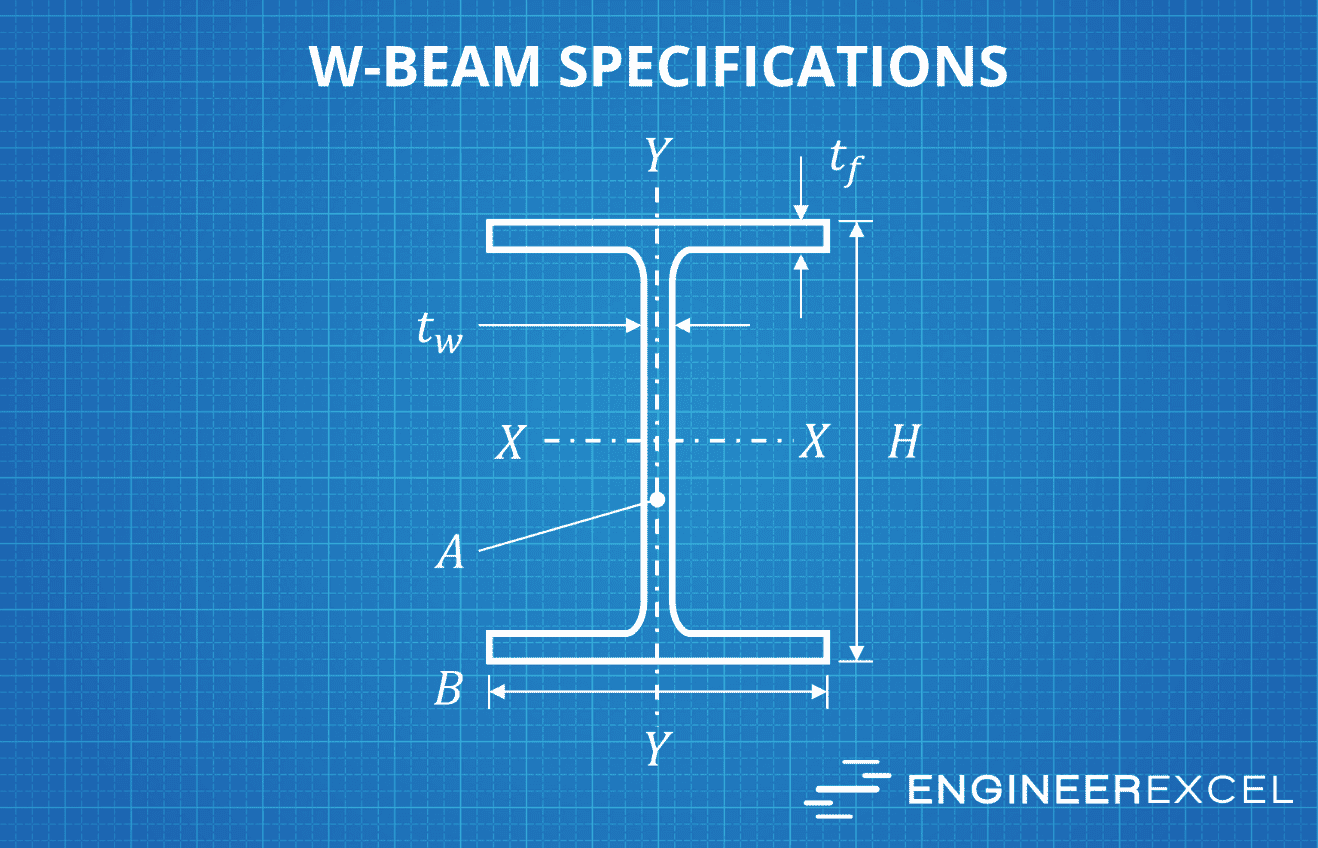
Flange Width (b): The width of the flange, which is the flat horizontal surface on the top and bottom of the beam.
Flange Thickness (tf): The thickness of the flange at its thickest point, typically near where the flange connects to the vertical web.
Web Thickness (tw): The thickness of the vertical center section, known as the web.
When referring to W-beam sizes, it is important to consider not only the dimensions but also the structural properties, such as the moment of inertia and section modulus. These properties play an essential role in the beam’s ability to resist loads and bending. Below is a brief overview of these properties:
- Moment of Inertia (Ix): A measure of an object’s resistance to angular acceleration when subjected to bending.
- Section Modulus (Sx): The cross-sectional property that quantifies the beam’s ability to resist bending stresses. This value is the ratio of the moment of inertia to the distance from the extreme fiber to the neutral axis.
Engineers and architects use these values to determine the appropriate beam size for a specific design load and application. By understanding the standard notation and calculating these structural properties, one can efficiently and accurately select the optimal W-beam for any given project.
Difference Between W-Beams, I-Beams, and S-Beams
“I-beam” is a general term for several standardized beam designations including W-beams and S-beams. These beams have different shapes, sizes, and stress distribution properties, so they are suitable for different applications.
W-Beams: Also known as a wide-flange beam, W-beams have wide flanges and a web connecting them. The flange width is typically much larger than I-beams, which provides more surface area to resist lateral loads. Wide-flange beams possess a parabolic but irregular shear stress distribution with a jump at the flange-to-web junctions. Thanks to their wider flanges and the shape of their webs, W-beams demonstrate higher resistance to bending and twisting, making them ideal for use in large construction projects such as buildings, bridges, and towers.
S-Beams: Sometimes referred to as standard beams or junior beams, S-beams are like W-beams in cross-sectional shape but have a smaller flange width. The reduced flange width results in lower lateral load resistance and a smaller moment of inertia compared to W-beams. S-beams are most used in applications with less stringent loading requirements, such as building frames, support columns, and conveyor systems.
Materials Used in W-Beam Manufacturing
The most common material used is carbon steel, which offers a combination of high strength and affordability. The steel grades used in the production of W-beams are categorized by their yield strength and tensile strength, with higher grades offering better performance. Some commonly used steel grades for W-beams include A36, A992, and A572. These grades can be further enhanced by quenching and tempering or adding additional elements such as manganese and silicon.
Below is a table comparing the properties of some common steel grades used in W-beams:
| Steel Grade | Yield Strength (ksi) | Tensile Strength (ksi) |
| A36 | 36 | 58-80 |
| A572 | 42-65 | 60-80 |
| A992 | 50 | 65 |
Mechanical and Structural Properties of W-Beams
There are various mechanical and structural properties that characterize W-beams.
Dimensions and shapes: W-beams come in a variety of sizes and shapes, typically denoted by their nominal depth and weight per foot. Both ASTM and the American Institute of Steel Construction (AISC) provide a standard range of W-beam sizes.
Material properties: W-beams are generally made from mild steel, with the most common grade being A36 steel. This material has a yield strength of 36 ksi (kilopounds per square inch) and a tensile strength of 58-80 ksi, making it suitable for various applications that demand both strength and ductility. Other grades, such as A992 steel, can also be used for W-beams.
Loads and stresses: W-beams can be subjected to different types of loading, including uniformly distributed loads, point loads, and moment loads, among others. The response of the beam to these loads can be analyzed using shear and moment diagrams, which will provide valuable information on the internal forces and bending moments within the beam. These stresses further help in determining the appropriate size and material of the W-beam for a specific structure.
Deflection and stiffness: Deflection is an essential consideration for the design of a W-beam since it influences both the performance and serviceability of a structure. Engineers calculate the deflection by considering the material’s modulus of elasticity, the beam’s moment of inertia, and the applied loads. The stiffness of a W-beam is primarily governed by its geometry, including its cross-sectional area and shape. Higher stiffness results in lower deflections under the same loading conditions.
W-Beam Production Process
The production process of W-beams involves various steps to transform raw materials into the finished product.
The initial stage involves steel rolling, wherein flat metal sheets are rolled into the desired shape. The steel goes through various stages of rolling using a series of rolling stands; each stand applies specific levels of pressure and deformation to achieve the desired profile. The final profile comprises two flanges and a web, forming an “I”-shape.
Once the steel has been rolled into the required profile, it is subject to heat treatment. This involves heating the steel to a specific temperature and then cooling it rapidly or slowly, depending on the desired properties. This process helps to improve the beam’s strength, hardness, and tensile characteristics.
Finally, the beams may undergo surface treatment to enhance corrosion resistance, paint adhesion, and appearance. This may include processes such as shot blasting, painting, or galvanizing. The finished beams are then packaged, labeled, and shipped to customers for their intended applications.
Standard Practices and Regulations for W-Beam
W-beams, also known as wide-flange beams, are commonly used structural members in buildings and bridges. They possess notable strength and stiffness properties that make them an ideal choice for withstanding vertical and lateral loads. The design, fabrication, and installation of W-beams are governed by industry-standard practices and regulations to ensure their structural integrity and safety.
The American Institute of Steel Construction (AISC) is a key organization responsible for developing and maintaining design standards for steel structures, including W-beams. AISC provides guidelines for the selection, design, and fabrication of W-beams in its publications such as the “Steel Construction Manual” and the “Specification for Structural Steel Buildings.”
Some critical aspects that are addressed in these guidelines include:
- Material selection: W-beams are manufactured from several different steel grades.
- Dimensions and properties: W-beams are classified by their nominal depth, flange width, and weight per unit length. These parameters, along with other geometric properties like web and flange thicknesses, affect the beam’s capacity to resist bending and shear forces.
- Design procedures: The AISC’s guidelines specify methods for calculating the required W-beam size to resist loads (dead, live, wind, seismic, etc.) imposed on a structure. These methods consider factors like load combinations, load duration, slenderness limits, and structural analysis approaches.
- Connections: W-beams are connected to other structural elements through various methods, such as welding or bolting. AISC provides detailed guidelines for designing and detailing these connections to ensure their structural performance.
- Fabrication: Fabrication practices related to cutting, drilling, and maintaining the dimensional tolerances of W-beams are also detailed in AISC guidelines. These guidelines help ensure that beams maintain their designed strength and stiffness characteristics.