
A U-tube manometer is a simple device for measuring fluid pressure. It consists of a U-shaped tube filled with a liquid, and the pressure difference between the two arms of the U-tube is determined by the difference in the levels of the liquid in each arm.
In this article, we will discuss how to use a U-tube manometer to measure pressure, as well as its components, installation and measurement guidelines, and applications.
What is a U-Tube Manometer
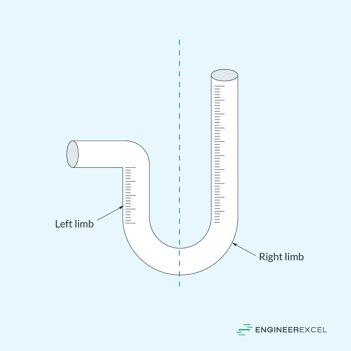
The U-Tube Manometer is a U-shaped tube utilized for measuring the pressure difference between two points. The left portion of the manometer, with a right-angled opening pointed to the side, is referred to as the left limb, while the right portion, with an opening pointed upwards, is known as the right limb, as shown in the diagram below.

Elevate Your Engineering With Excel
Advance in Excel with engineering-focused training that equips you with the skills to streamline projects and accelerate your career.
The left limb of the U-tube is usually connected to the container holding the fluid to be measured, while the other end is open to the atmosphere. The lower part of the U-tube contains a liquid, known as the manometric fluid, that has a greater density and does not mix with the fluid to be measured.
The U-tube manometer operates on the principle that when two pressures are applied to the ends of the tube, the liquid inside the tube moves to balance the weight of the liquid column due to the pressure differential. The height difference between the two liquid columns is therefore proportional to the pressure difference.
For example, if the pressure inside the container is higher than the atmospheric pressure, then the height of the manometric fluid in the left limb is lower than the right limb, as shown in the diagram below.
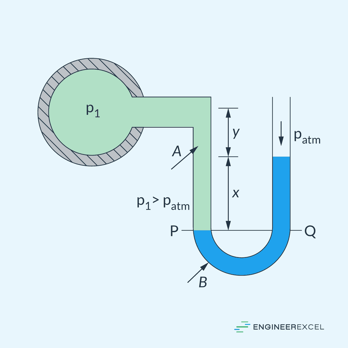
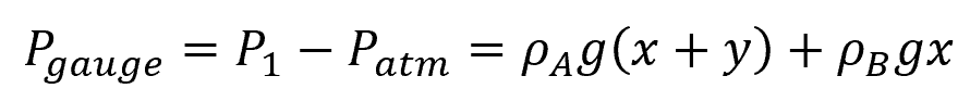
In this case, the U-tube manometer is measuring gauge pressure, which can be calculated using the formula:
Where:
- Pgauge = gauge pressure inside the container [Pa]
- P1 = absolute pressure inside the container [Pa]
- Patm = atmospheric pressure [101325 Pa]
- ρA = density of the fluid inside the container [kg/m3]
- ρB = density of the manometric fluid [kg/m3]
- g = acceleration due to gravity [9.81 m/s2]
- x = difference in height between the manometric fluid in the left and right limbs [m]
- y = difference in height between the container and the highest point of the manometric fluid [m]
Otherwise, if the pressure inside the container is lower than the atmospheric pressure, then the height of the manometric fluid in the left limb is higher than the right limb, as shown in the diagram below.
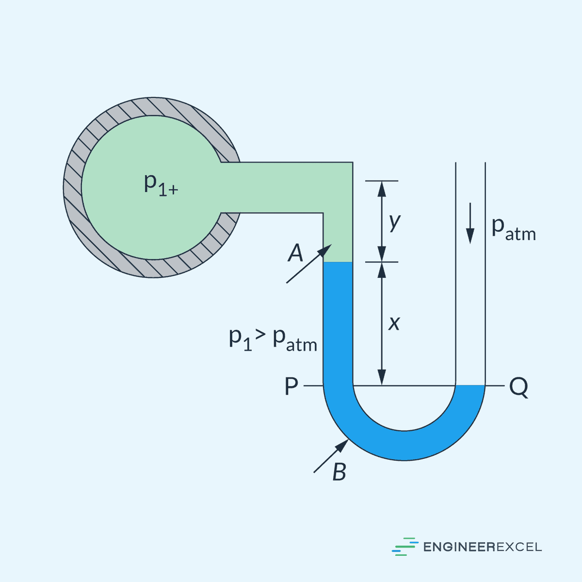
In this case, the U-tube manometer is measuring vacuum pressure, which can be calculated using the formula:
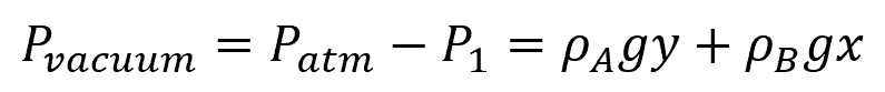
Where:
- Pvacuum = vacuum pressure inside the container [Pa]
Manometers offer high levels of accuracy for in-situ calibration and are valued for their simplicity and reliability. However, the user must account for fluid properties and environmental conditions to avoid inaccuracies.
It is essential to note that the accuracy of a U-tube manometer can be affected by several factors. The diameter of the tube should be sufficiently large to neglect capillary effects. Moreover, the liquid should be incompressible and non-evaporating. Any deviation from these conditions can lead to erroneous readings.
The U-tube manometer provides a practical and reliable method to gauge pressure differences in fluid mechanics, highlighting the direct relationship between fluid column height and pressure.
Design and Components
Transparent Tube
The transparent tube is the main body of a U-tube manometer, typically made of glass or clear plastic, allowing for the visible detection of fluid levels. This component is shaped in a “U” form, ensuring that both ends are vertically aligned, which is crucial for accurate readings.
Fluid
The fluid within the U-tube manometer must have a known density and is often chosen based on the type of pressure being measured. Commonly used fluids include water, mercury, and oil. The manometric fluid’s incompressibility and ability to translate pressure into a readable height differential in the tube are key to the manometer’s function.
Scale
Attached to or imprinted along the U-tube is a scale, often graduated in millimeters or inches, which allows for precise measurement of the fluid column displacement. Accurate calibration of the scale is essential, as it converts the height difference directly into units of pressure.
Installation and Measurement Guidelines
When installing a U-tube manometer, it is essential to follow a precise set of guidelines to ensure accurate pressure measurements.
Location
Select a location where the manometer can be vertically mounted and easily read, while remaining close to the pressure source. The manometer should be securely attached to a stable, vibration-free wall or panel using brackets.
Filling the Manometer
Ensure that the U-tube is clean and dry. Use a funnel in transferring the manometric fluid into the tube to minimize spillage and air bubbles.
Note that the manometer fluid must be compatible with the system to prevent chemical reactions or absorption.
Connecting to the Pressure Source
Attach the manometer to the pressure source with airtight connections. Use appropriate seals or threading tapes. Check for leaks by applying a slight pressure and using a leak detector solution.
Leveling the Manometer
Adjust the mount to ensure the manometer is perfectly vertical, using a plumb line or spirit level. Set the manometer to zero by adjusting the fluid level to the reference mark when no pressure is applied.
Final Checks
Confirm that the manometer provides accurate readings by comparing it with a known pressure source. Ensure that the setup complies with safety regulations, especially when using hazardous fluids such as mercury.
Reading Measurements
For precise readings, external factors such as temperature and capillary effects should be considered as they can influence fluid density and surface tension. The capillary effects can be ignored if the U-tube diameter is large enough. Remember that the reading is independent of the manometer tube diameter, provided these effects are negligible.
Applications
U-tube manometers are simple instruments widely utilized in various settings to measure pressure differences. They are commonly used in HVAC systems, laboratory experiments, and diverse industrial processes.
HVAC Systems
In heating, ventilation, and air conditioning (HVAC) systems, U-tube manometers serve a critical function by ensuring accurate pressure measurements for system calibration and troubleshooting. They aid technicians in assessing the pressure levels within ductwork and verifying the proper operation of the HVAC components.
Laboratory Experiments
Educational and research laboratories employ U-tube manometers to demonstrate and study fluid dynamics and pressure relationships. They are ideal for experiments due to their ability to measure small pressure changes with a high degree of accuracy, which is essential in controlled scientific studies.
Industrial Processes
U-tube manometers are integral to monitoring and controlling process pressures in various industrial applications, from chemical production to oil and gas refineries. Their design allows for the reliable measurement of pressure differences, which is key to maintaining the safety and efficiency of complex industrial systems.