
An isentropic process is a thermodynamic process in which entropy remains constant. This implies that the process is reversible and adiabatic, meaning there is no heat exchange with the surroundings and the entropy change is zero.

In this article, we will discuss the characteristics of isentropic processes, including their property diagrams, isentropic relationships, and isentropic efficiencies of various devices.
What is Isentropic Process
Entropy is a parameter that measures the degree of dispersion and randomness in the distribution of energy and mass within a system. Unlike path functions such as heat or work, entropy is a state function similar to temperature or pressure. This means that changes in entropy are solely determined by the initial and final state entropies, independent of the specific path followed during the transition.
An isentropic process refers to a thermodynamic process during which the entropy of a system remains constant. This means that a substance’s entropy at the end of the process will be the same as its beginning, as shown in the example below.

Elevate Your Engineering With Excel
Advance in Excel with engineering-focused training that equips you with the skills to streamline projects and accelerate your career.
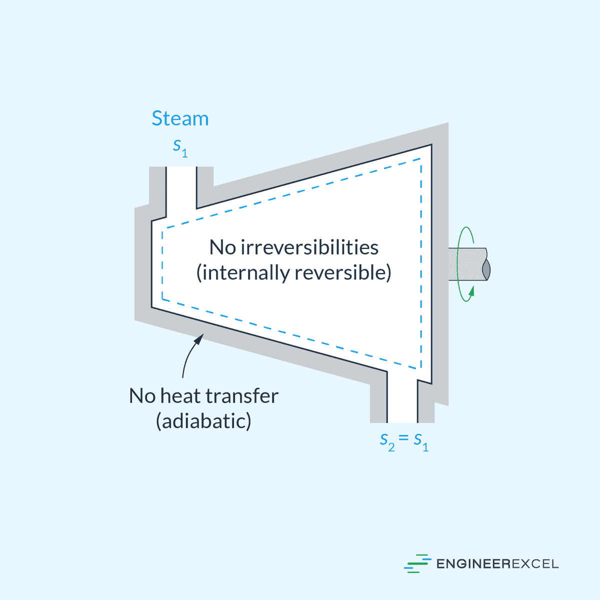
Isentropic processes are typically characterized by internal reversibility and adiabatic conditions, indicating the absence of heat transfer. However, it’s important to clarify that an isentropic process doesn’t always equate to a reversible adiabatic process.
While a reversible adiabatic process must be isentropic, an isentropic process can exist even if it’s not reversible adiabatic. This can happen when the increase in entropy caused by irreversibilities is counterbalanced by a decrease in entropy resulting from heat losses. Nonetheless, the term “isentropic process” is commonly used in thermodynamics to refer to an internally reversible, adiabatic process.
Many engineering devices, including pumps, turbines, nozzles, and diffusers, can be modeled as isentropic during their operation. This can be used as a basis for defining efficiencies in thermodynamic analyses, providing a benchmark for comparing the actual performance of these devices to their performance under idealized conditions.
Property Diagrams of Isentropic Process
Temperature-Entropy (T-s) Diagram
In the T-s diagram, an isentropic process is represented by a vertical line, as shown below.
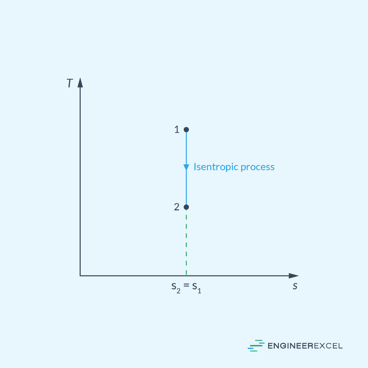
The temperature (T) can vary along the vertical line, indicating changes in temperature during the process. However, the entropy remains constant.
Pressure-Volume (P-v) Diagram
In the P-v diagram, an isentropic process is represented by a curve characterized by the following equation:

Where:
- P = pressure [Pa]
- v = volume [m3]
- k = adiabatic index [unitless]
This is illustrated in the diagram below.
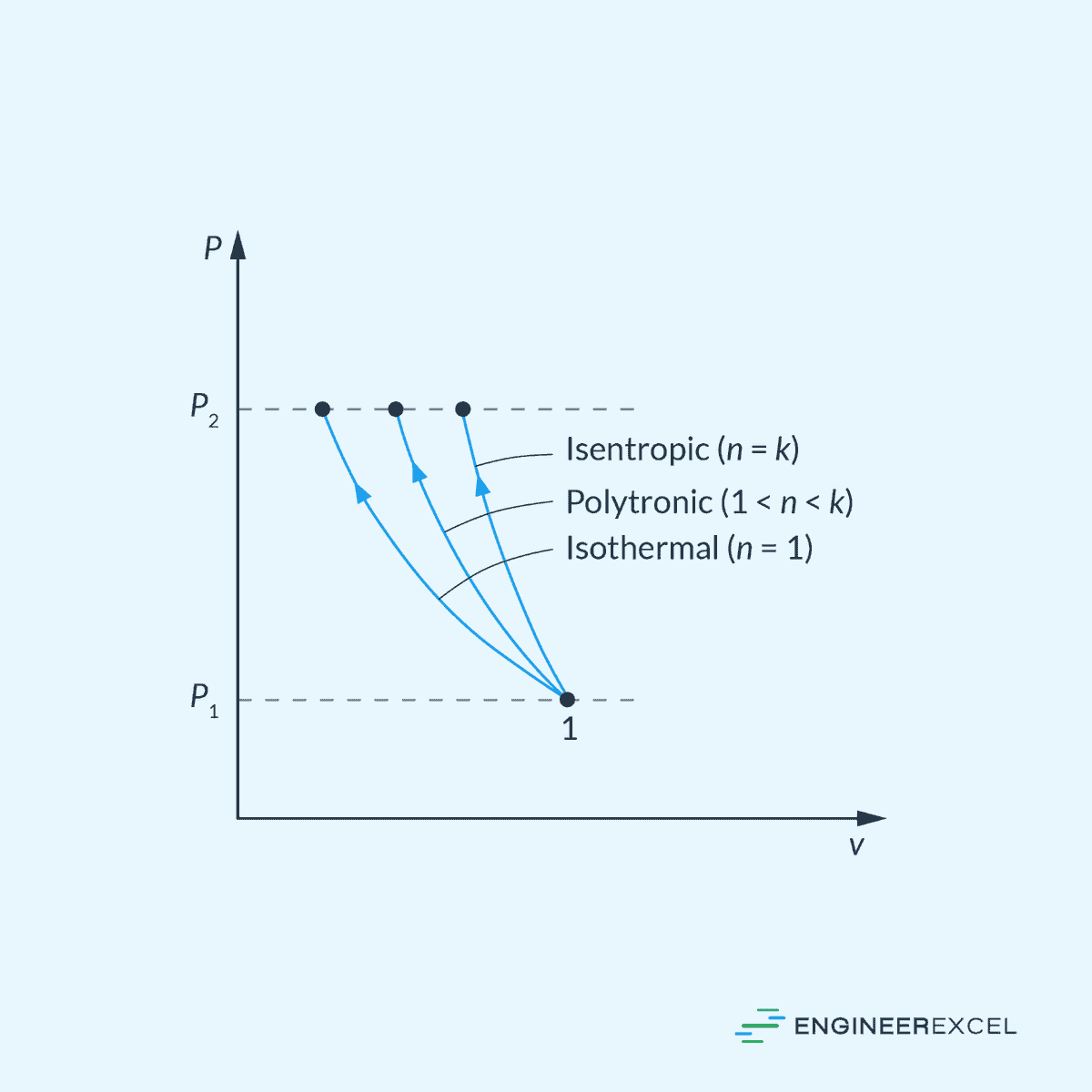
Remember that the adiabatic index (k) is simply equal to the ratio of the constant-pressure specific heat to the constant-volume specific heat.
Isentropic Relationships
Liquids and Solids
Liquids and solids can be considered as incompressible substances because their densities remain nearly constant during a process. In this case, the entropy change during a process is given by:
Where:
- s1, s2 = initial and final specific entropy [J/kg-K]
- cavg = average specific heat [J/kg-K]
- T1, T2 = initial and final temperature [K]
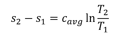
For isentropic process, s1 and s2 are equal. Hence, the above equation reduces to:
Therefore, the isentropic process for liquids and solids is also isothermal.
Ideal Gases
Assuming constant specific heats, the entropy change for ideal gases can be calculated using the following equations:
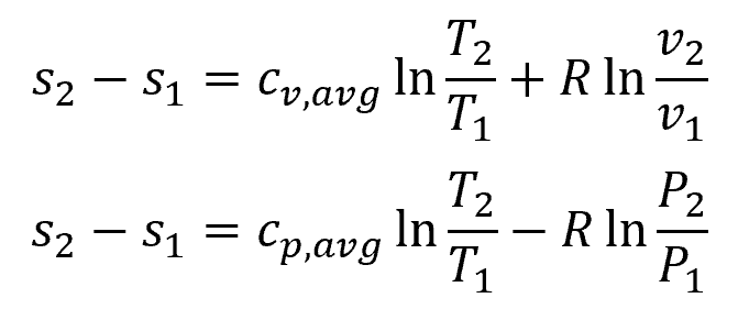
Where:
- cv,avg = average constant-volume specific heat [J/kg-K]
- cp,avg = average constant-pressure specific heat [J/kg-K]
- v1, v2 = initial and final specific volume [m3/kg]
- P1, P2 = initial and final pressure [Pa]
By setting both of these equations equal to zero, several relations can be obtained for isentropic process in ideal gases as follows:

Isentropic Efficiency
The isentropic efficiency is defined as the ratio of the actual performance of a device to its idealized isentropic performance. A higher isentropic efficiency indicates a closer approach to the idealized process and signifies a more effective and less energy-wasting operation. It is commonly used in thermodynamics to assess the performance of devices like steam turbines, gas compressors, and nozzles.
Turbines
The isentropic efficiency of a turbine is the ratio of the actual work output to the work output that would be achieved if the process between the inlet state and the exit pressure were isentropic. This can be mathematically expressed as:
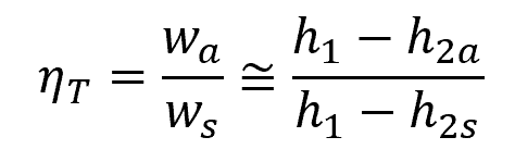
Where:
- ηT = isentropic efficiency of a turbine [unitless]
- wa = actual work [J/kg]
- ws = isentropic work [J/kg]
- h1 = enthalpy value at the inlet state [J/kg]
- h2a = actual enthalpy value at the outlet state [J/kg]
- h2s = isentropic enthalpy value at the outlet state [J/kg]
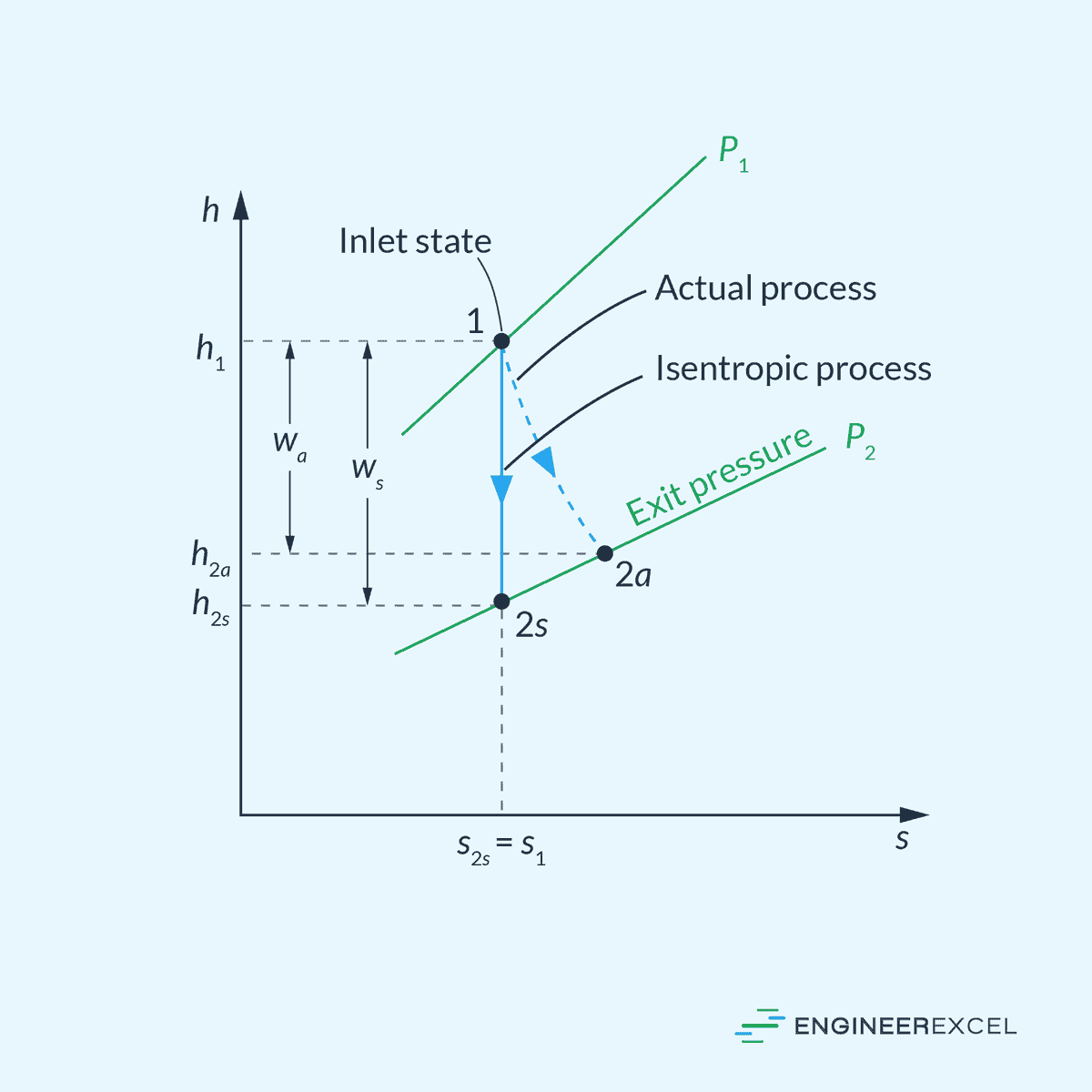
This is illustrated in the enthalpy-entropy diagram below.
Compressors and Pumps
The isentropic efficiency of a compressor is the ratio of the work input required to raise the pressure of a gas to a specified value in an isentropic manner to the actual work input. This can be mathematically expressed as:
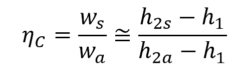
Where:
- ηC = isentropic efficiency of a compressor [unitless]
This is illustrated in the enthalpy-entropy diagram below.
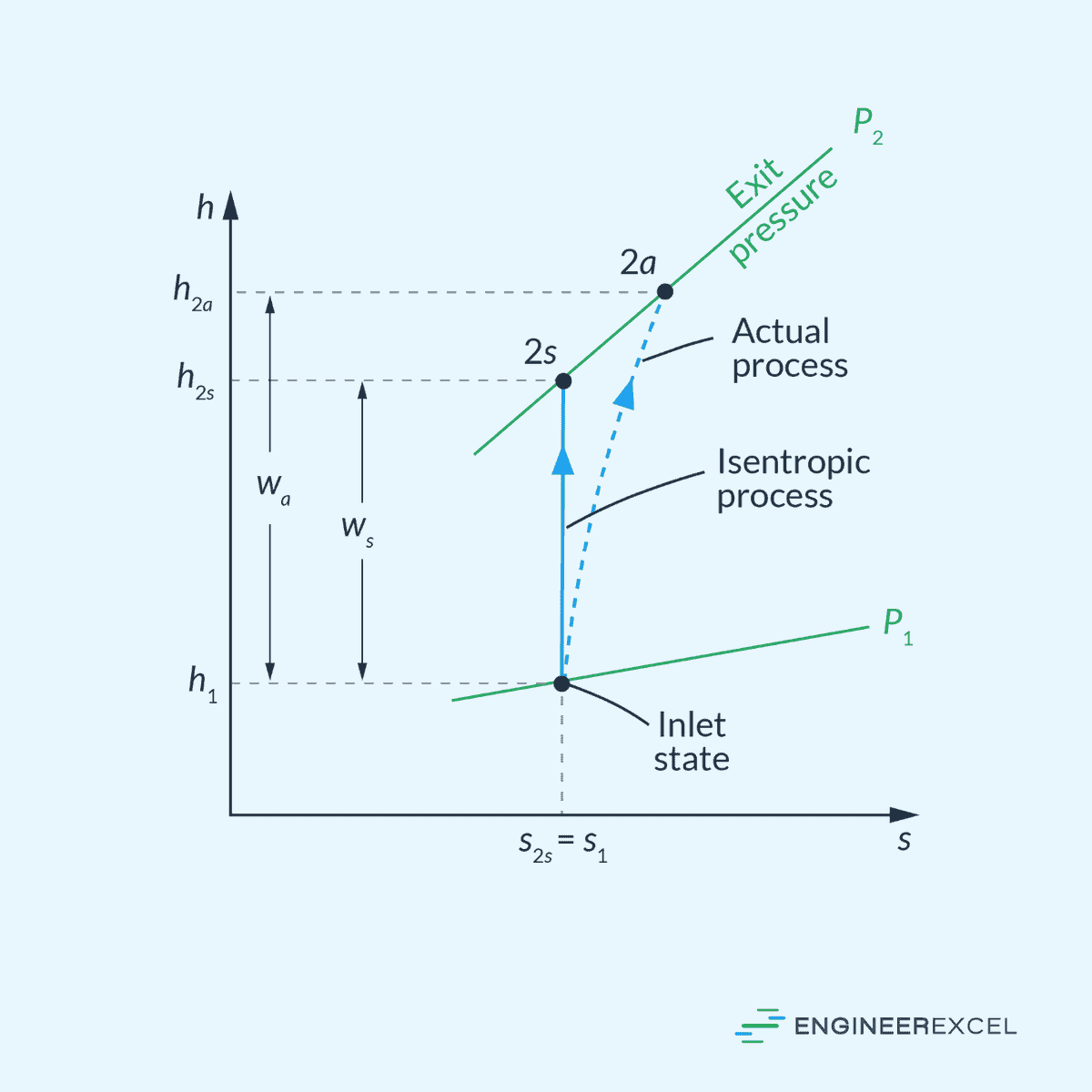
Nozzles
The isentropic efficiency of a nozzle is the ratio of the actual kinetic energy of the fluid at the nozzle exit to the kinetic energy value at the exit of an isentropic nozzle for the same inlet state and exit pressure. This can be mathematically expressed as:
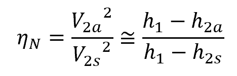
Where:
- ηN = isentropic efficiency of a nozzle [unitless]
- V2a = actual velocity at nozzle exit [m/s]
- V2s = isentropic velocity at nozzle exit [m/s]
This is illustrated in the enthalpy-entropy diagram below.
