Flywheels are mechanical devices that consist of a rotating heavy disk or wheel designed to store and release kinetic energy in the form of rotational motion. This ability to act as an energy reservoir has made flywheels essential in smoothing out the flow of energy across diverse machinery like reciprocating engines, wind turbines, and braking systems, among others.
This article explores the fundamental principles of flywheels, their working mechanism, and the calculations involved in determining flywheel energy.
Flywheel Energy Calculation
Flywheels are used to store mechanical energy for future use. They achieve this by employing a heavy disk with a high moment of inertia, which effectively resists changes in rotational motion. When a force is applied to a flywheel, it converts that energy into angular momentum as it starts to rotate.
Elevate Your Engineering With Excel
Advance in Excel with engineering-focused training that equips you with the skills to streamline projects and accelerate your career.
Flywheels are a type of accumulator, which is a general term for devices that accept, store, and release energy as required. Examples of other accumulators include steam accumulators, mainsprings, inductors, and capacitors. Like other types of accumulators, a flywheel acts as a low-pass filter, smoothing out deviations in the power output of a system.
Consider an engine power train with a flywheel connected to one end of the crankshaft, shown below. The flywheel is used to store energy during each firing so that whenever there is a decrease in power input, the stored energy in the flywheel contributes to a surge in power output. Conversely, it absorbs any excess power input in the form of rotational energy.
A flywheel can be a spinning wheel, disc, or rotor, rotating around its symmetry axis. Assuming that the flywheel has a fixed mass and radius, then the amount of stored rotational energy is directly proportional to the square of its rotational speed. The kinetic energy can be calculated using the formula:
Where:
- E = stored rotational kinetic energy [J]
- I = mass moment of inertia about the flywheel’s axis of symmetry [kg-m2]
- ω = angular velocity of the flywheel [rad/s]
Note that a flywheel’s mass moment of inertia is a measure of its resistance to torque and is dependent on its mass and radius. The higher the moment of inertia, the slower it will accelerate when a given torque is applied.
Flywheels can have various shapes. The method for calculating their moment of inertia depends on the specific geometry of the flywheel.
For a solid cylinder, which is the most commonly used shape for steel rotors, the mass moment of inertia can be calculated using the formula:
Where:
- m = mass of the flywheel [kg]
- r = radius of the flywheel [m]
On the other hand, for a hollow circular cylinder, the mass moment of inertia can be calculated using the formula:
Where:
- ro = outer radius of the hollow cylinder [m]
- ri = inner radius of the hollow cylinder [m]
When dealing with a flywheel that consists of a rim, hub, and spokes, it is common practice to estimate the moment of inertia by assuming that each component contributes a fixed percentage to the overall moment of inertia.
Maximum Angular Velocity
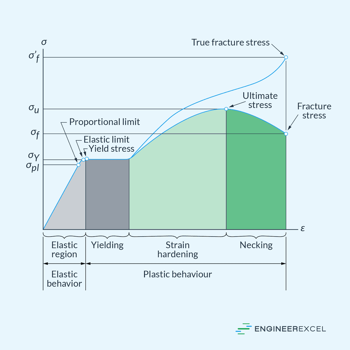
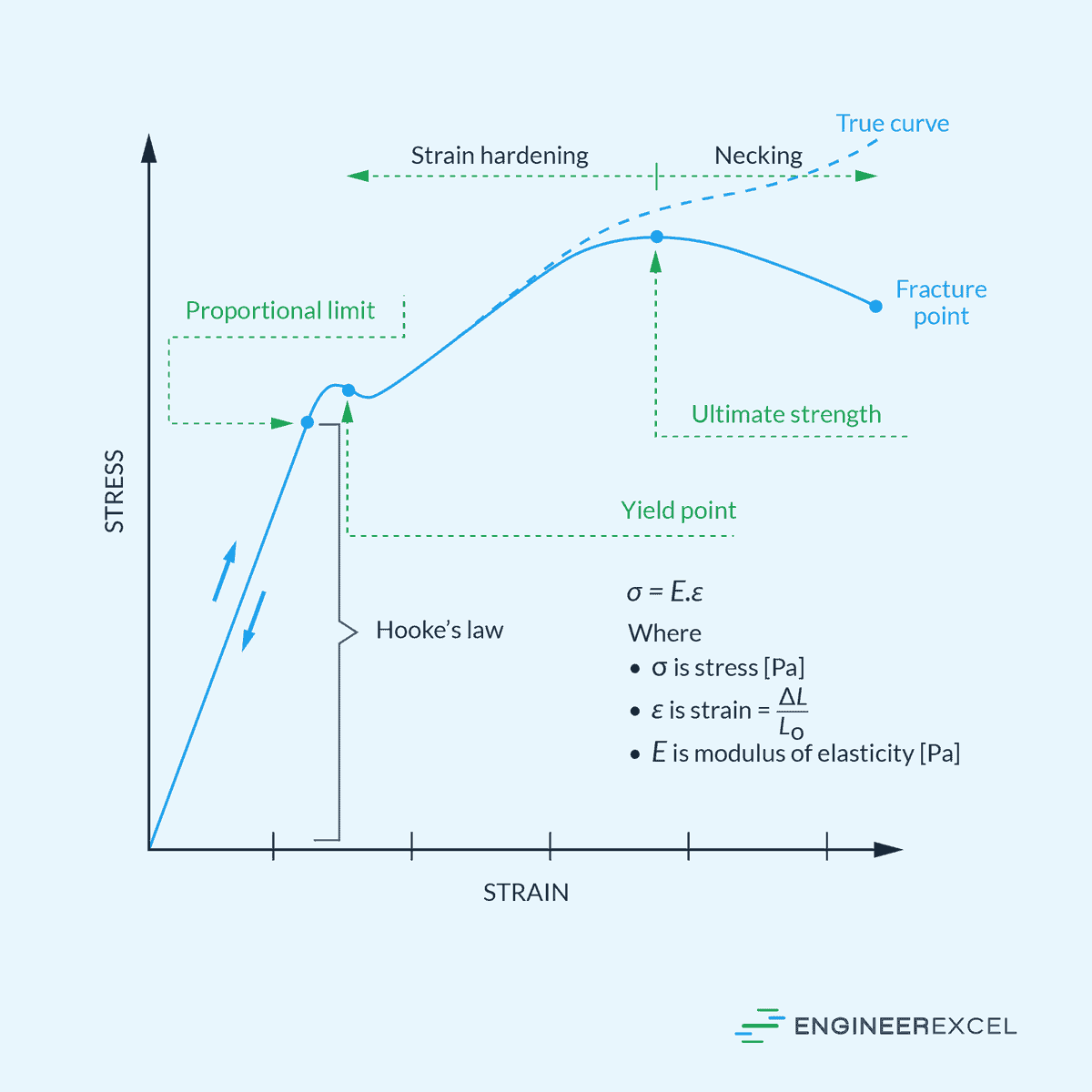
According to the energy equation mentioned above, the stored kinetic energy of a flywheel with a fixed mass and geometry can only be increased by raising the rotational speed. However, it is important to note that as the rotational speed increases, so do the stresses within the flywheel.
If these stresses surpass the material’s tensile strength, the flywheel is at risk of fracturing or breaking apart. Hence, the amount of energy that a flywheel can store is restricted by its tensile strength.
In line with this, the maximum allowable angular velocity can be calculated using the formula:
Where:
- ω = maximum allowable angular velocity [rad/s]
- σ = tensile hoop strength of the flywheel material [N/m2]
- ρ = density of the flywheel material [kg/m3]
Therefore, the best materials for flywheels are those with high tensile strength and low density.
Note that the equation provided above does not account for friction losses. In practical applications, measures are taken to minimize friction and energy losses by enclosing the flywheel within a vacuum chamber and using magnetic bearings as an alternative to mechanical bearings.
Flywheel Stress Distribution
Aside from the maximum allowable angular velocity, it can be valuable to examine the distribution of radial and hoop stresses across the flywheel. Assuming the material is isotropic, the radial and hoop stress distributions for a thin rim that rotates freely can be calculated using the following formula:
Where:
- r = variable radius [m]
- σr = radial stress at radius r [N/m2]
- σh = hoop stress at radius r [N/m2]
- ν = Poisson’s ratio of the material [unitless]
- ri = internal diameter of the rim [m]
- ro = outer diameter of the rim [m]
In practice, the stress distribution of a flywheel is analyzed and simulated using finite element analysis.
Maximum Energy Density
A useful measure for assessing the efficiency of a flywheel is its maximum energy density, which represents the maximum amount of energy the flywheel can store per unit mass. For a given flywheel design, the maximum energy density can be related to its tensile strength and material density using the formula:
Where:
- emax = maximum energy density [J/kg]
- Emax = maximum amount of kinetic energy that the flywheel can store [J]
- K = shape factor of the flywheel [unitless]
The shape factor is dependent on the geometry of the flywheel. The most common geometries and cross-sections for flywheels are shown on the table below.
The choice of flywheel material with the highest specific tensile strength is essential for achieving optimal energy storage per unit mass. This is why materials like carbon fiber are of particular interest, as they offer high strength-to-weight ratios.
However, certain applications require the flywheel to operate at a specific angular velocity and fit within a confined space. In such cases, rather than solely focusing on energy density, the objective is to maximize the stored energy per unit volume. Hence, the selection of materials for the flywheel depends on the specific requirements of the application.
It is also important to understand that the calculated maximum energy stored in a flywheel is not equivalent to the maximum energy it can release. In most designs, a maximum drop in rotational speed of 50% is allowed. As a result, the maximum available energy that can be expended is usually around 75% of the stored energy, meaning the depth of discharge is 75%.
Ultimately, the energy storage capability of a flywheel is primarily determined by its geometry and speed, while the power capabilities are influenced by the motor-generator and power electronics employed.
Flywheel Applications
Flywheels’ ability to efficiently store and release energy makes them valuable in fields such as energy storage, transportation, and mechanical systems.
In energy storage systems, flywheels can be used to store excess energy generated from renewable sources like wind or solar power. When there is a demand for electricity, the stored energy in the flywheel can be released to the grid, helping to balance power supply and demand and improving the overall stability of the electrical system. They can also be used to stabilize the grid by responding to fluctuations in power supply and demand.
Flywheel energy storage (FES) systems have seen advancements with the use of carbon-fiber composite rotors. Suspended by magnetic bearings within a vacuum enclosure, these high-strength, low-density rotors enable flywheels to rapidly achieve the necessary angular speed in just a matter of minutes. In general, FES systems can reach energy capacity much faster compared to other storage methods.
In hybrid vehicles, flywheels can be used to capture energy during braking by converting it into rotational motion. This energy is then released during acceleration, reducing the load on the engine and resulting in improved fuel efficiency. This is also useful in industrial machinery or equipment that requires intermittent bursts of power.
Flywheels are also extensively used in gyroscopes— devices that can maintain orientation and resist changes in rotational direction that are crucial for navigation. Flywheels in gyroscopes provide stability by maintaining a constant rotational speed and resisting external forces, enabling accurate measurement of angular velocity and precise orientation control.