
In piping systems, reducers are fittings used to connect pipes of different sizes or diameters. When designing systems that use reducers, one of the ways to calculate the pressure loss across them is using the concept of equivalent lengths.
In this article, we discuss the equivalent length of reducers, its calculation, and the different types of reducers.
Understanding Equivalent Length of Reducers
Reducers are fittings used to connect pipes of different sizes or diameters. In piping systems, they help maintain proper pressure and flow rates by preventing turbulence, which can occur when transitioning between different pipe sizes. They also aid in system flexibility and adaptability, enabling the integration of different equipment or components with varying pipe connections.
Reducers can be designed to transition from a larger pipe size to a smaller one or vice versa. Because of the change in their inlet and outlet flow areas, they cause a change in fluid pressure and velocity, which typically leads to losses. These losses can be quantified using the concept of equivalent lengths.

Elevate Your Engineering With Excel
Advance in Excel with engineering-focused training that equips you with the skills to streamline projects and accelerate your career.
The equivalent length of a reducer is a value that represents the pressure drop cause by the reducer in terms of an equivalent length of straight pipe with the same diameter. In other words, it translates the energy loss in a reducer into a pipe length that would cause an equal amount of pressure drop.
The term “equivalent length” originates from the Darcy-Weisbach equation, which calculates the head loss (pressure drop) in a pipe due to friction, and is expressed in linear units, such as meters or feet. This concept is useful for engineers since it enables them to account for the total losses in a piping system without diving into the complicated details of individual fittings.
In order to calculate for the total head losses of a piping system, the equivalent lengths of all the valves and fittings, including reducers, are typically added to the actual length of straight pipes in order to obtain a hypothetical length of straight pipe that would yield the same total system head losses, as follows:
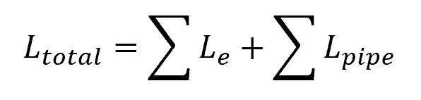
Where:
- Ltotal = hypothetical total length of pipe including equivalent lengths [m]
- Le = equivalent length of each valve and fitting [m]
- Lpipe = actual length of straight pipes [m]
Using the total length computed, the total system head loss can be calculated using the Darcy-Weisbach equation:
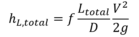
Where:
- hL,total = total system head loss [m]
- f = Darcy friction factor [unitless]
- D = pipe diameter [m]
Calculating the Equivalent Length of Reducers
The equivalent length of reducers depends on various factors such as flow conditions, reducer size, and pipe material. There are different approaches to calculating this value. A common method involves determining the loss coefficient and calculating the equivalent length using the following formula:
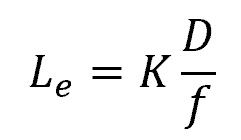
Where:
- K = loss coefficient [unitless]
The loss coefficient is a dimensionless value that indicates the pressure loss across the reducer. It depends on the geometry of the reducer and the flow conditions.
On the other hand, the Darcy friction factor is a dimensionless parameter that measures the resistance to flow in the straight pipe being used as a basis in determining the equivalent length. It is influenced by the pipe’s roughness, Reynolds number, and flow regime.
Using the above equation, the equivalent length of a specific reducer can be experimentally determined. While tables of equivalent lengths are sometimes available, keep in mind that these values are for standard fittings made of specific materials and tested under controlled conditions. Real-world installations may exhibit deviations due to factors like surface roughness and manufacturing tolerances, which might affect the accuracy of the equivalent length method.
Types of Reducers
There are two common types of reducers: concentric reducers and eccentric reducers.
Concentric Reducers
Concentric reducers have a symmetrical design that aligns the centerlines of the larger and smaller pipe sections, as shown in the diagram below. These reducers are typically used when there is no need to maintain the same top or bottom level of the pipeline.
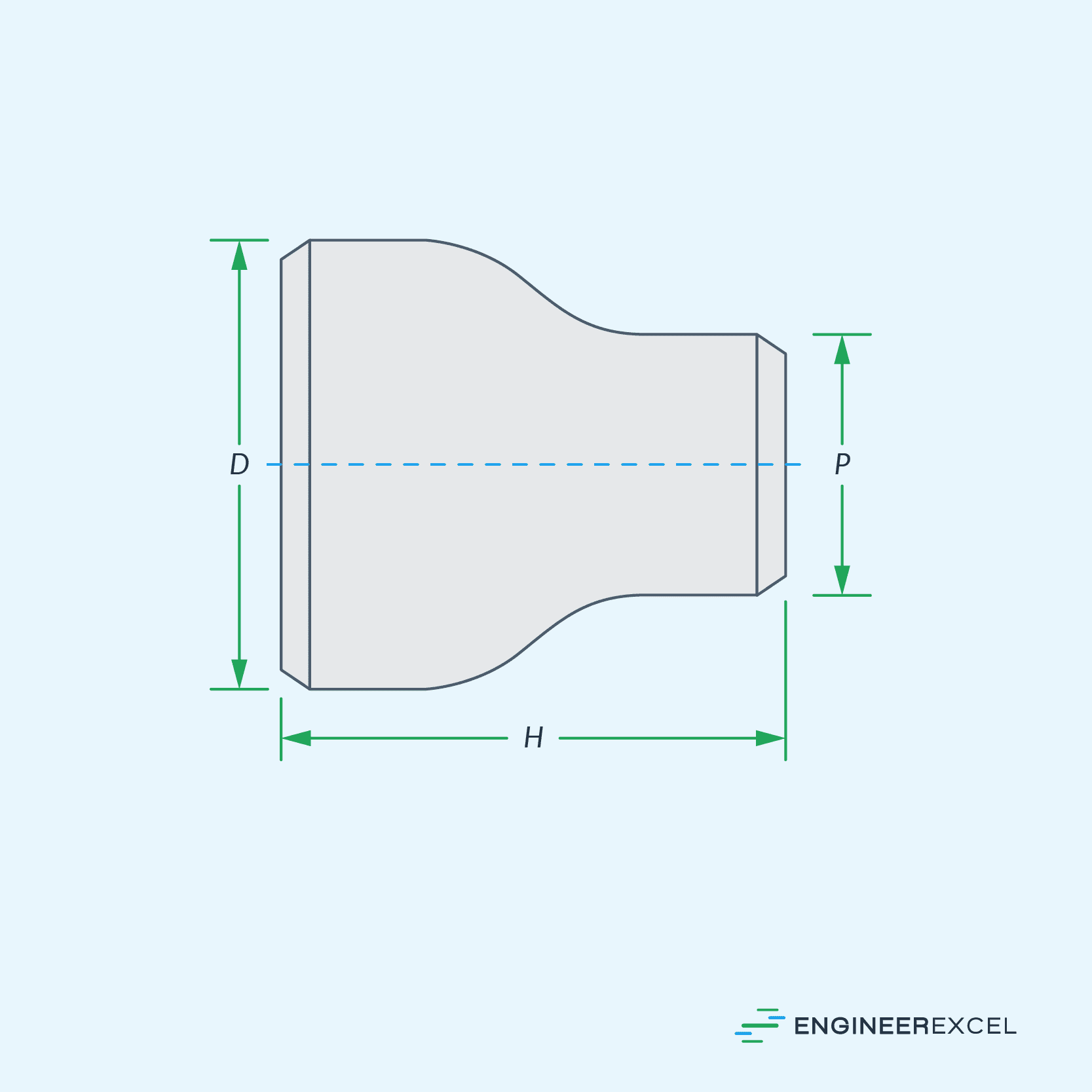
The major advantage of concentric reducers is the smooth and gradual change in diameter, which minimizes turbulence and pressure loss. However, concentric reducers may lead to air or gas pockets forming if used in a horizontal pipeline.
Eccentric Reducers
Unlike concentric reducers, eccentric reducers have an offset that aligns either the top or the bottom of the two pipes, as shown in the diagram below. This eliminates the risk of air or gas pockets forming, making them suitable for horizontal pipelines, particularly in fluid flow applications where air entrapment is undesirable.

Eccentric reducers generally experience more pressure loss than concentric reducers due to their geometry. Hence, they generally have higher equivalent lengths for the same size.