
Accurate measurement of flow is important in many industries, from water supply systems to chemical processing plants. One commonly used device for measuring fluid flow is the Venturi tube.
This article explains how a Venturi tube operates and how it can be used to measure flow.
How Does a Venturi Tube Work
A Venturi tube, also called as a Venturi meter, is a type of differential pressure flow meter that measures flow by introducing a constriction along the pipeline and then measuring the pressure difference induced across the constriction to obtain flow rate. The concept of the Venturi tube is based on Bernoulli’s principle.
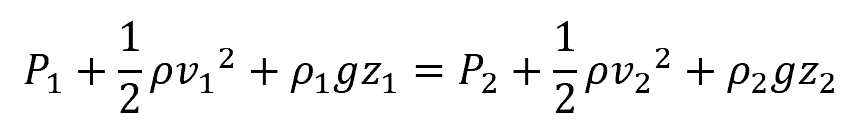
Bernoulli’s principle states that within a flowing fluid, an increase in the fluid’s velocity is accompanied by a decrease in pressure, and conversely, a decrease in velocity is accompanied by an increase in pressure. This is shown in the following equation:

Elevate Your Engineering With Excel
Advance in Excel with engineering-focused training that equips you with the skills to streamline projects and accelerate your career.
Where:
- P1, P2 = pressure of the fluid at different points along a streamline [Pa]
- v1, v2 = velocity of the fluid at different points [m/s]
- z1, z2 = elevation of the fluid at different points [m]
- ρ = density of the fluid [kg/m3]
- g = acceleration due to gravity [9.81 m/s2]
By introducing a constriction along the pipeline, a Venturi tube creates regions with different velocities, leading to a measurable pressure difference that can be used to calculate flow rate.
As shown in the diagram below, a Venturi tube consists of three sections: a converging section, a throat, and a diverging section.
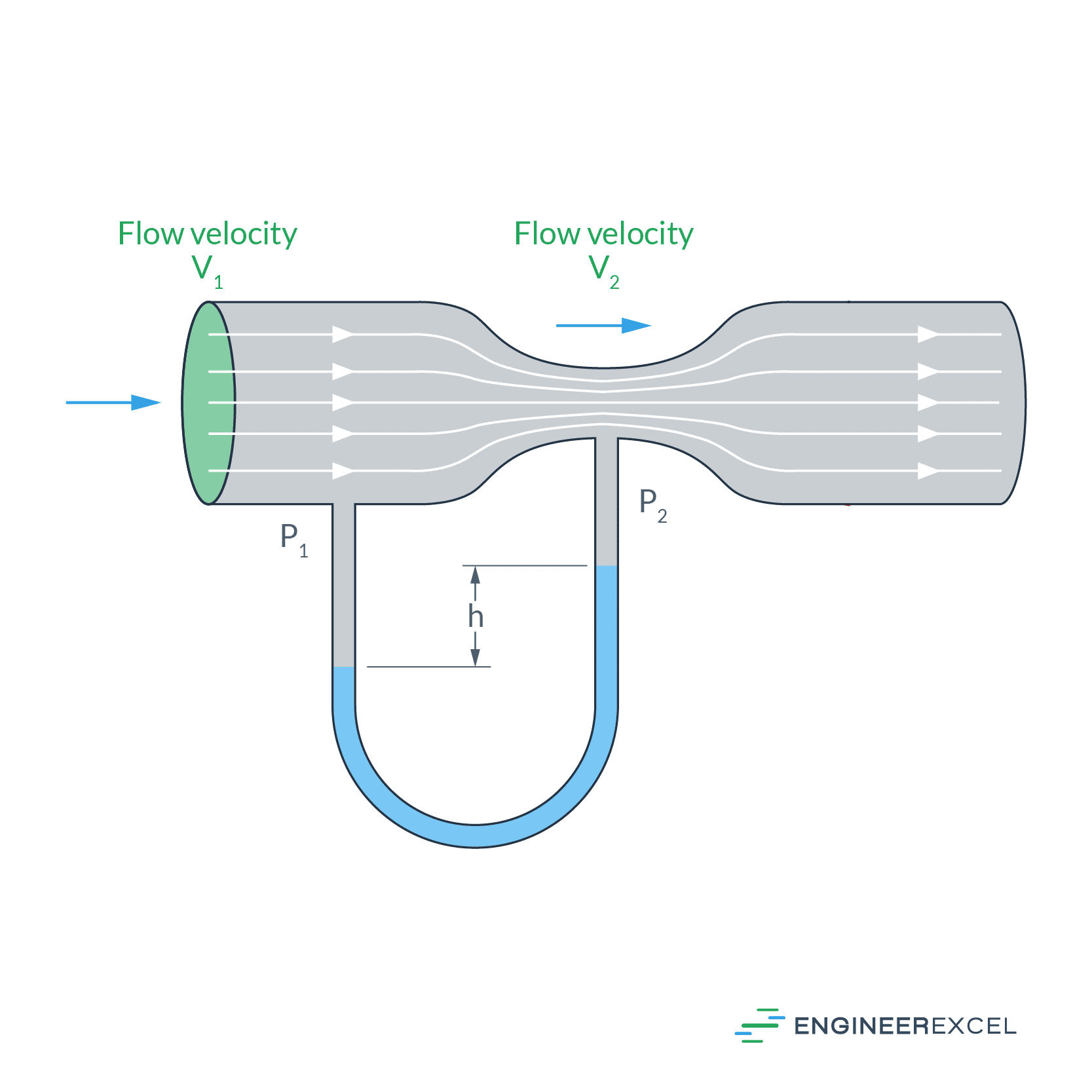
Fluid enters the Venturi tube through the converging section, where it gradually gains velocity due to the decreasing cross-sectional area of the tube. At the end of the converging section is the throat, where the fluid reaches maximum velocity and minimum pressure. After passing through the throat, the fluid slows down again due to the increasing cross-sectional area at the diverging section, allowing the pressure to recover.
Measuring Flow Using Venturi Tube
To measure flow rate using a Venturi tube, pressure taps are typically installed at the inlet and the throat sections, as shown in the diagram below.
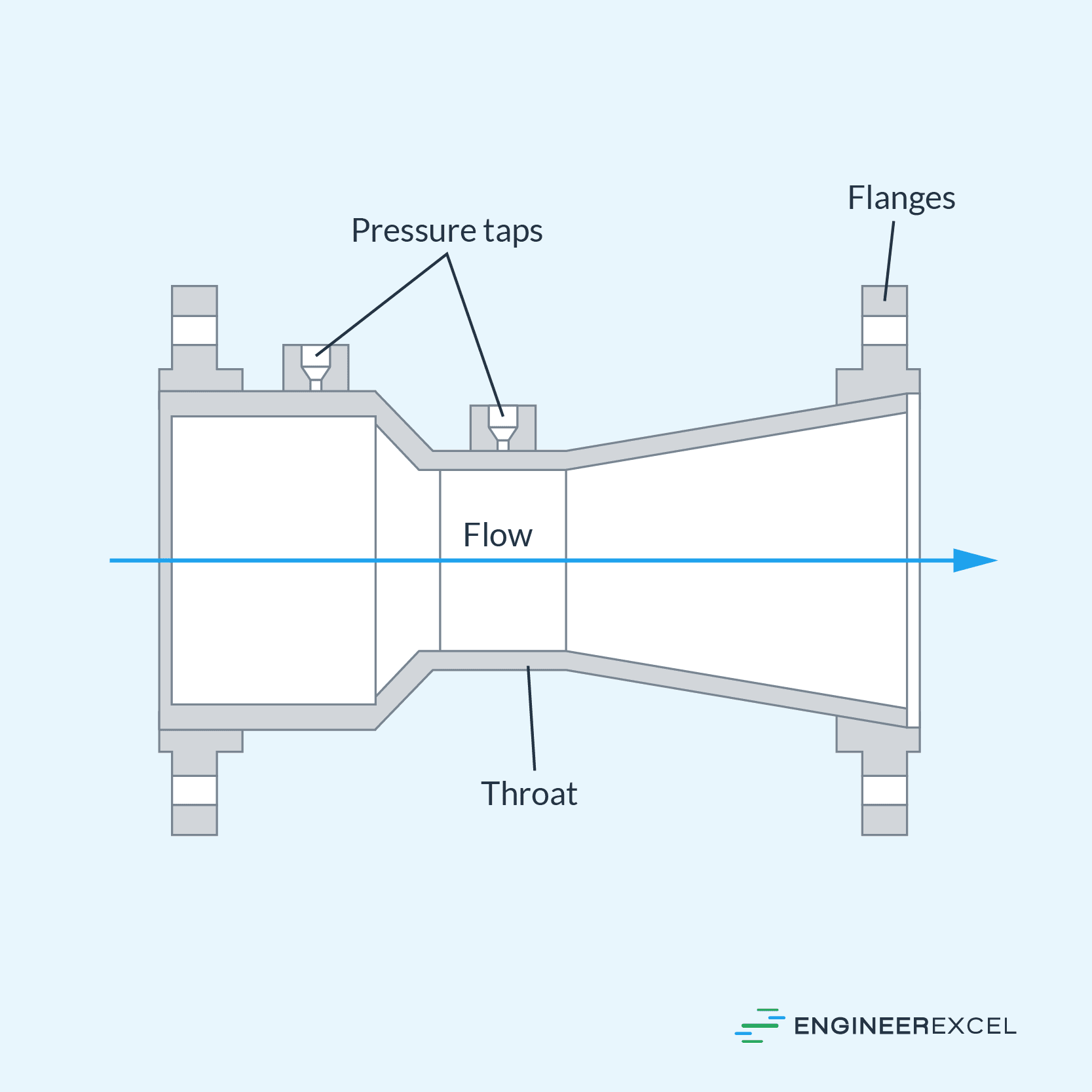
To be specific, the pressure taps are positioned precisely at the midpoint of the throat and at half a pipe diameter upstream of the converging section. The pressure difference between the inlet and the throat is measured using a differential pressure transducer or manometer. Once the pressure difference is obtained, the fluid velocity and flow rate can be calculated.
Using the Bernoulli’s principle, the ideal fluid velocity at the throat can be calculated using the following formula:
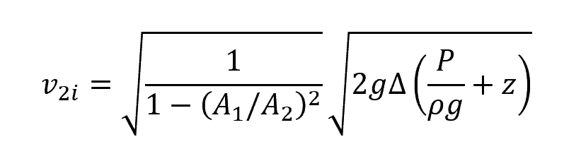
Where:
- v2i = ideal fluid velocity at the throat [m/s]
- A1 = cross-sectional area of the pipe at the inlet [m2]
- A2 = cross-sectional area of the throat [m2]
- Δ(P/ρg +z) = pressure difference between the inlet and the throat [Pa]
The above formula is only applicable for incompressible fluids. However, if the Mach number of the flow is less than 0.1, a compressible fluid can be treated as incompressible without introducing significant errors in measurement.
Also note that the above formula only calculates the ideal velocity. The actual velocity is slightly less than the ideal velocity because of the effects of friction. In practical applications, a dimensionless parameter, called the discharge coefficient, is used to account for the friction losses and other factors.
The formula for the volumetric flow rate then becomes:
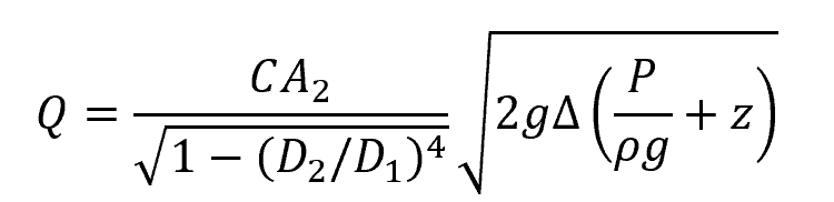
Where:
- Q = volumetric flow rate [m3/s]
- C = discharge coefficient [unitless]
- D1 = inlet diameter [m]
- D2 = throat diameter [m]
The value of the discharge coefficient depends on the Reynolds number, geometry of the Venturi tube, fluid properties, and other factors. In general, the higher the Reynolds number, the higher the discharge coefficient.
This is illustrated in the graph below, showing the relationship between the discharge coefficient and Reynolds number of water at 72°F flowing through a Venturi tube with a diameter ratio of 0.5.
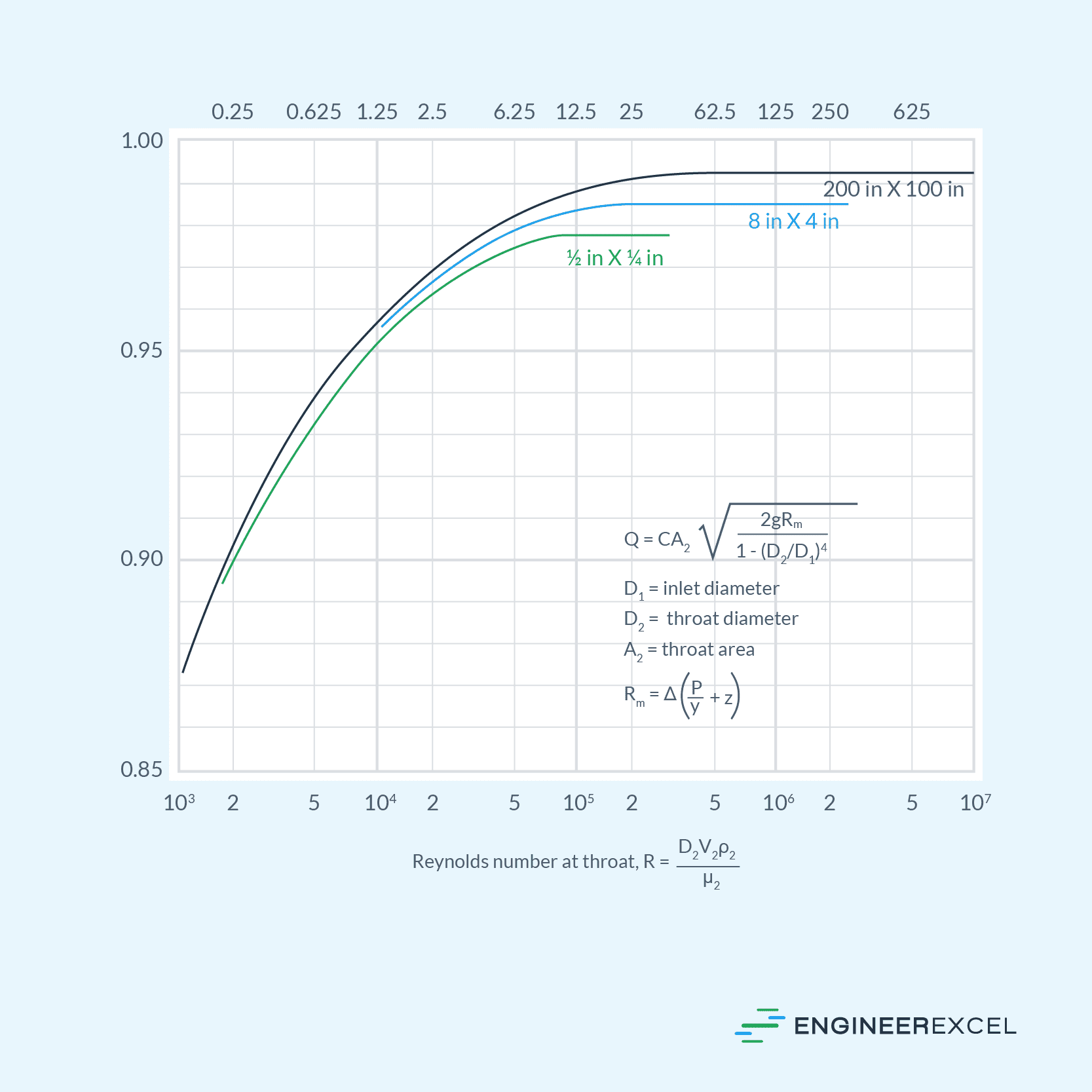
Provided the Reynolds number is greater than 105, the value of the discharge coefficient is normally assumed to be 0.99 for large tubes, and 0.97 or 0.98 for small tubes. However, this coefficient may decrease slightly due to surface roughness, especially in the case of older tubes or if scale buildup is present. It has been observed that Venturi tubes in long-term service experience a reduction in their discharge coefficient by approximately 1-2%.
If the Venturi tube is using a differential manometer with piezometric connections at the pressure taps, the following formula can be used to calculate for the volumetric flow rate:
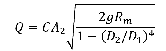
Where:
- Rm = manometer reading [Pa]
The ratio between the throat and inlet diameters typically varies between ¼ and ¾, but the most common ratio is ½. The smaller the ratio, the more accurate the reading. However, this also means higher friction loss.
Furthermore, if the throat becomes too constricted, cavitation may occur. This happens when the pressure of a liquid drops below its vapor pressure, causing the formation of vapor or cavities within the liquid.
For best accuracy, a Venturi tube is normally calibrated by measuring flow rate over a wide range of Reynolds numbers. It is also important to ensure that the Venturi tube is preceded by a straight pipe whose length is at least 5 to 10 pipe diameters, and that there are no nearby valves and fittings that may cause disturbance in the flow.
Uses of Venturi Tubes
Venturi tubes can be used in a wide range of applications including water treatment plants, oil and gas plants, and chemical processing. They are suitable for measuring flow rates across a broad spectrum — from small process streams to extremely large flow rates, with the only limiting factor being the pipe size. Typically, these tubes come in sizes ranging from ½ inch to 48 inches, though larger sizes have been built.
In addition, they can also be used for both incompressible and compressible fluids, including liquids, gases, vapors, and high-viscosity fluids. The Venturi tube’s streamlined design makes it suitable for challenging substances like dirty fluids, slurries, sludge, and gases with entrained liquids or solids that tend to accumulate in other flowmeters. However, it is important to protect the pressure taps from getting blocked.
Due to their structure, Venturi tubes are often more expensive and more challenging to fabricate and install compared to alternative differential flowmeters such as orifice plates and nozzles.
Nevertheless, their streamlined design allows them to have the lowest permanent pressure losses among the differential flowmeters. Hence, they are frequently used in applications that require conservation of energy. Most of these losses only happen at the diverging section of the tube.
Lastly, Venturi tubes boast a relatively high turndown ratio of up to 10:1. This turndown ratio defines the range between the maximum and minimum flow rates that it can accurately measure.
This means Venturi tubes work well for both low and high flow rates. They can even be used in situations with very low flow rates, like in labs or chemical dosing systems. Plus, they’re flexible in how they can be installed – horizontally, vertically, or at an angle.