
Hydraulic Motor Speed Calculator
Hydraulic Motor Torque Calculator
There are different types of motors depending on the energy source they utilize to generate motion. One of the most prevalent types is hydraulic motors, which convert hydraulic energy from pressurized fluids into rotational mechanical energy.

Elevate Your Engineering With Excel
Advance in Excel with engineering-focused training that equips you with the skills to streamline projects and accelerate your career.
This article delves into hydraulic motors, providing an in-depth understanding of how they work, the different types available, and the calculations involved in their design.
Hydraulic Motors
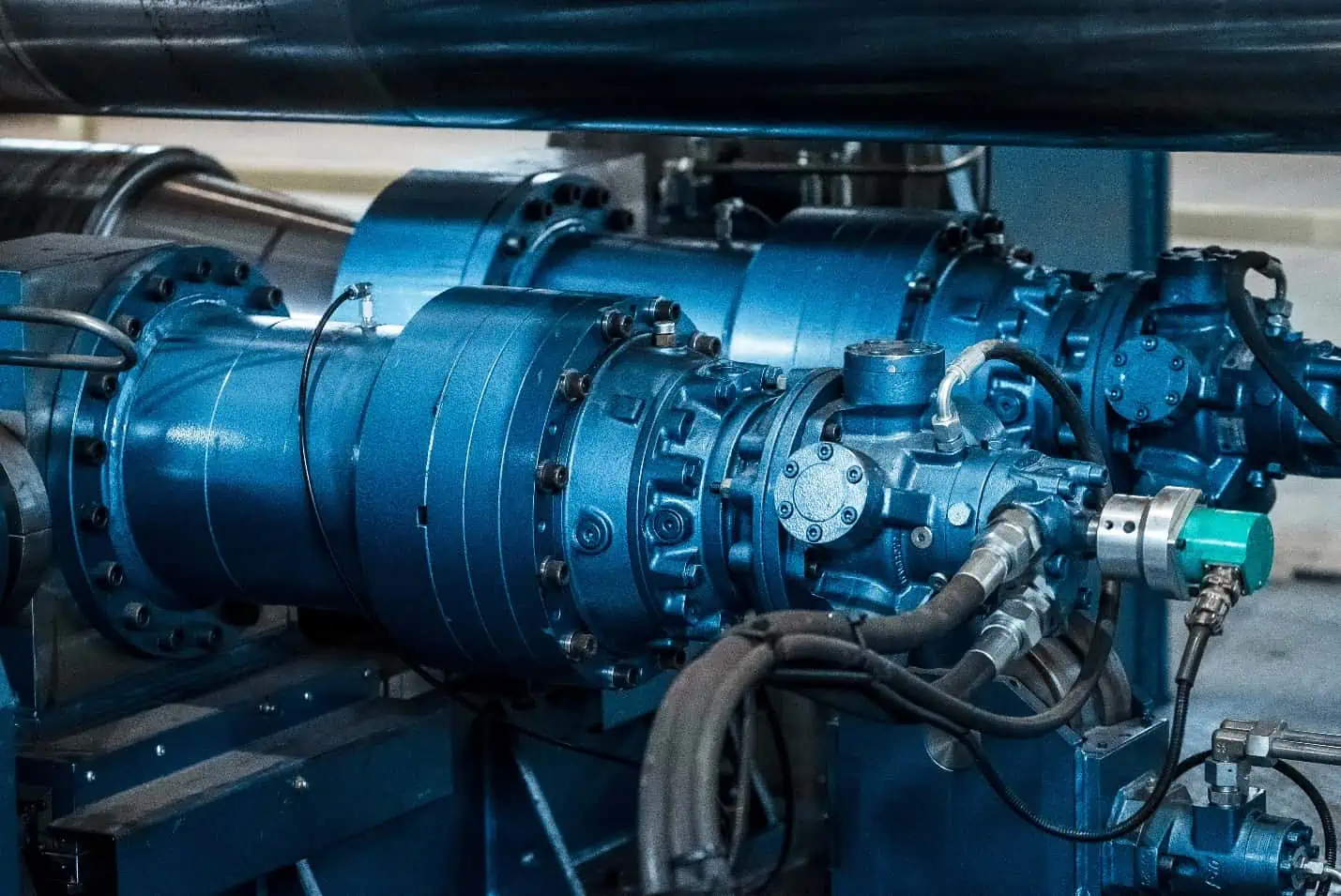
Hydraulic motors harness hydraulic energy from pressurized fluid to generate mechanical energy through rotational motion. They serve as the rotary counterpart to the hydraulic cylinder, which functions as a linear actuator.
They are known for their capacity to generate substantial torque at low speeds, making them particularly valuable in applications requiring heavy rotary movements. They are commonly employed in various heavy machinery, such as excavators, presses, conveyors, winches, and vehicles.
A typical hydraulic motor consists of four primary components: the rotor, which is responsible for producing rotational motion; the stator, which houses the rotor and guides the flow of fluid; valves and ports, which control fluid entry and exit to regulate flow; and the shaft, which connects to the rotor and transmits rotational motion to the load.
As pressurized hydraulic fluid enters the motor through its ports, it engages with the rotor, effectively converting pressure into torque. This torque is subsequently transmitted to a shaft connected to the load, allowing the motor to perform work via rotational motion. Hydraulic motors are considered positive displacement devices, meaning that they are designed to displace a specific volume of fluid or gas per rotation or cycle, regardless of the system pressure.
Types of Hydraulic Motors
Hydraulic motors can be classified into three primary types based on their configuration and operating principle: vane motors, gear motors, and piston motors.
Vane Hydraulic Motors
Vane hydraulic motors use vanes to generate torque by allowing the hydraulic pressure to push against the vanes exposed to the hydraulic fluid.
A typical vane hydraulic motor consists of a cylindrical housing containing a slotted rotor, vanes, and an output shaft. The rotor and vanes are mounted within the housing such that the vanes can slide in and out of the rotor connected to the drive shaft, as shown in the diagram below.
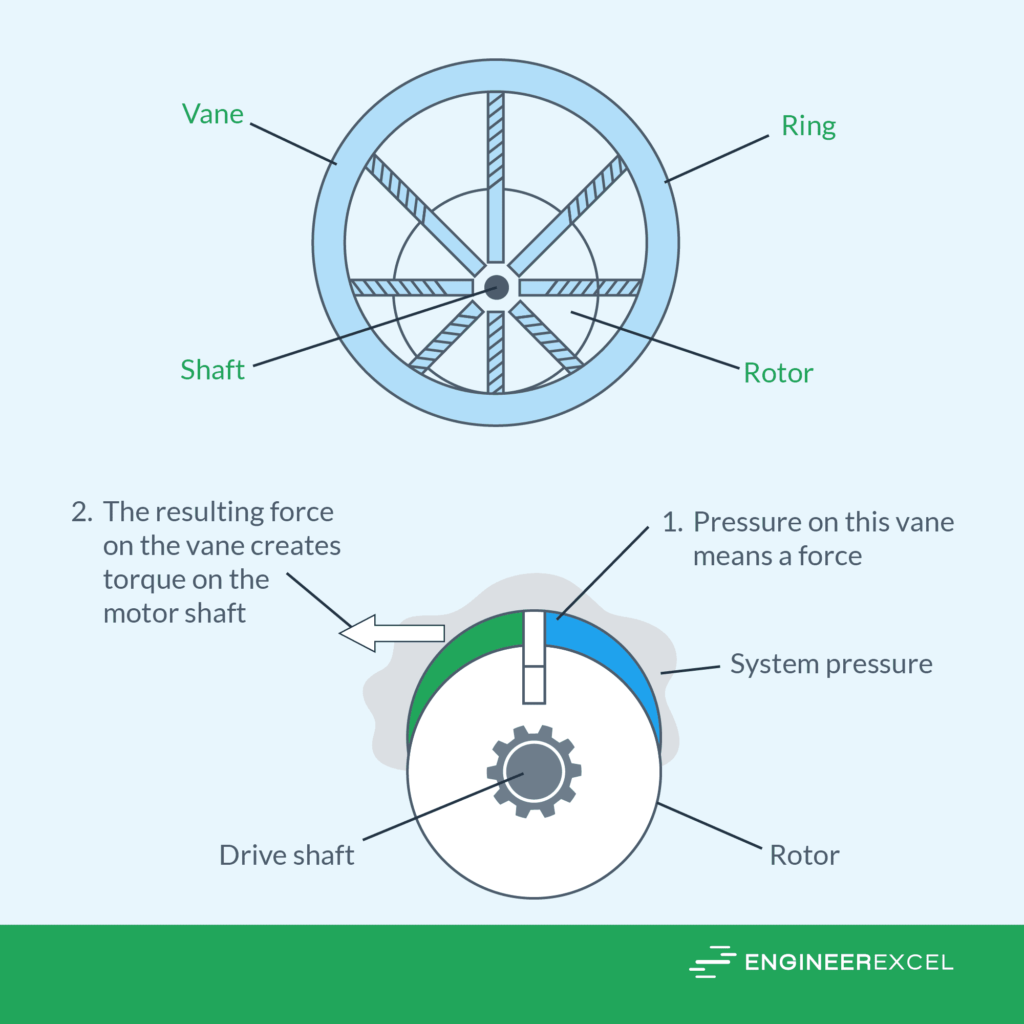
When hydraulic fluid enters the motor through an inlet port, it fills the chambers and exerts force on the vanes. These vanes stay in contact with the housing using springs that force them radially outward.
As the rotor starts to rotate, the volume inside the chambers decreases, resulting in the displacement of the hydraulic fluid. This displacement creates torque, effectively converting the hydraulic energy into rotational motion.
As the vanes slide in and out, they create sealed chambers within the motor, facilitating the flow of fluid from the inlet to the outlet port. In the case of a balanced vane motor design, the housing is equipped with two inlet and two outlet ports positioned 180 degrees apart, as shown in the diagram below.
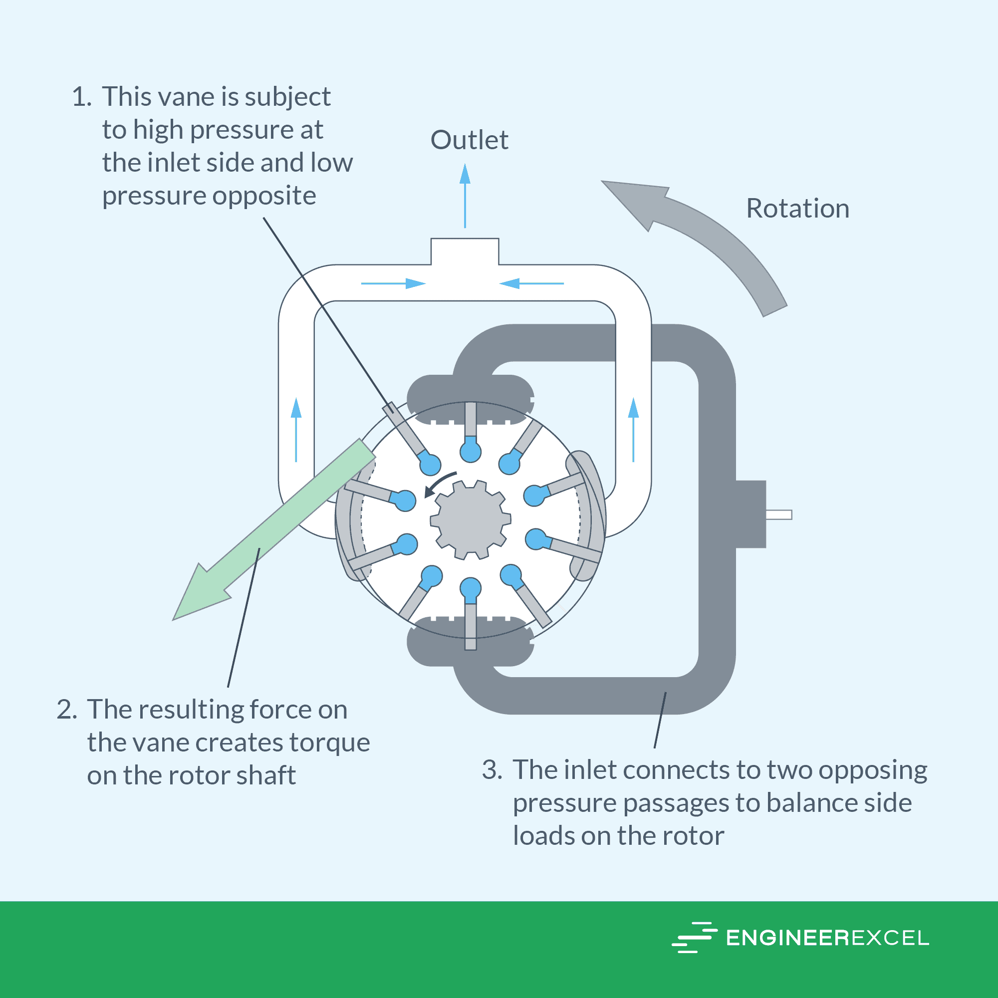
This configuration ensures that the two pressure quadrants counterbalance each other, effectively eliminating any imbalanced forces on the shaft. This leads to an enhanced stability and reliability of the motor’s operation.
In general, vane motors can operate at pressures up to 2500 psi, speeds up to 4000 rpm, and maximum flow delivery up to 250 gpm.
Gear Hydraulic Motors
Gear hydraulic motors use a system of gears within a sealed housing to convert hydraulic energy into rotary motion.
A typical gear hydraulic motor consists of a housing containing two or more gears, an inlet port, an outlet port, and an output shaft. The gears are designed to mesh with each other: the drive gear is attached to a shaft which is connected to a load, and the other gear is the driven gear. Generally, bigger gears or higher pressures result in greater shaft torque.
There are two primary configurations for gear motors: internal and external. An external gear motor uses meshing gears whose teeth are on their outer circumferences, as shown in the diagram below.
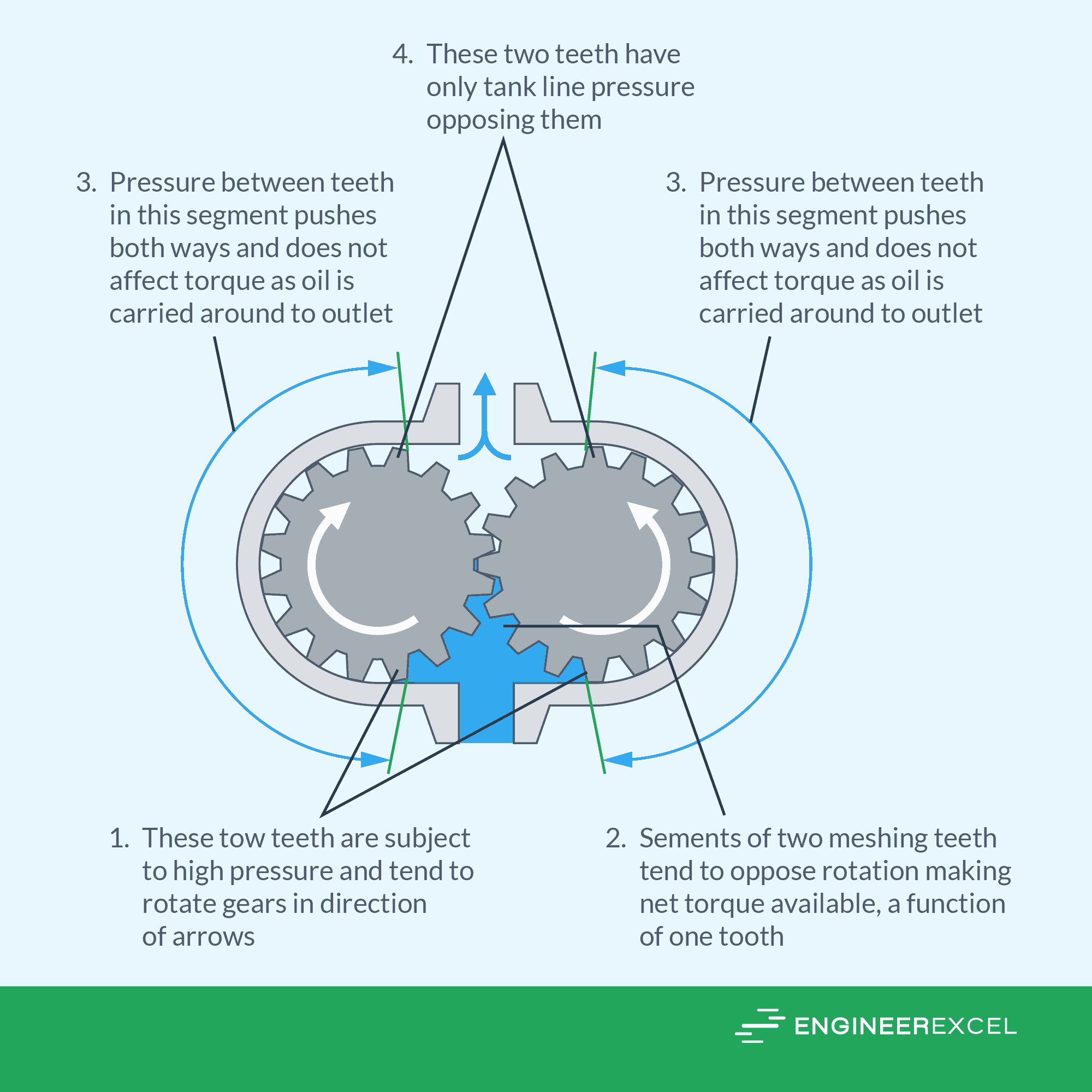
As the hydraulic fluid is supplied to the motor through an inlet port, it enters the housing and fills the spaces between the gear teeth. The teeth at the inlet side are subjected to high pressure, causing the gears to rotate in the direction shown in the diagram above.
Note that the gears are intentionally designed to rotate in a manner where they unmesh, rather than mesh, as fluid enters the housing. This is because gears which mesh generate a decreasing volume which would result in the fluid being pushed out of the housing. Hence, the gears have no alternative but to unmesh in order to accommodate the entering fluid.
On the other hand, an internal gear motor has one external gear which meshes with the teeth on the inside circumference of a larger gear. A popular variation of an internal gear is the gerotor motor, shown in the diagram below.
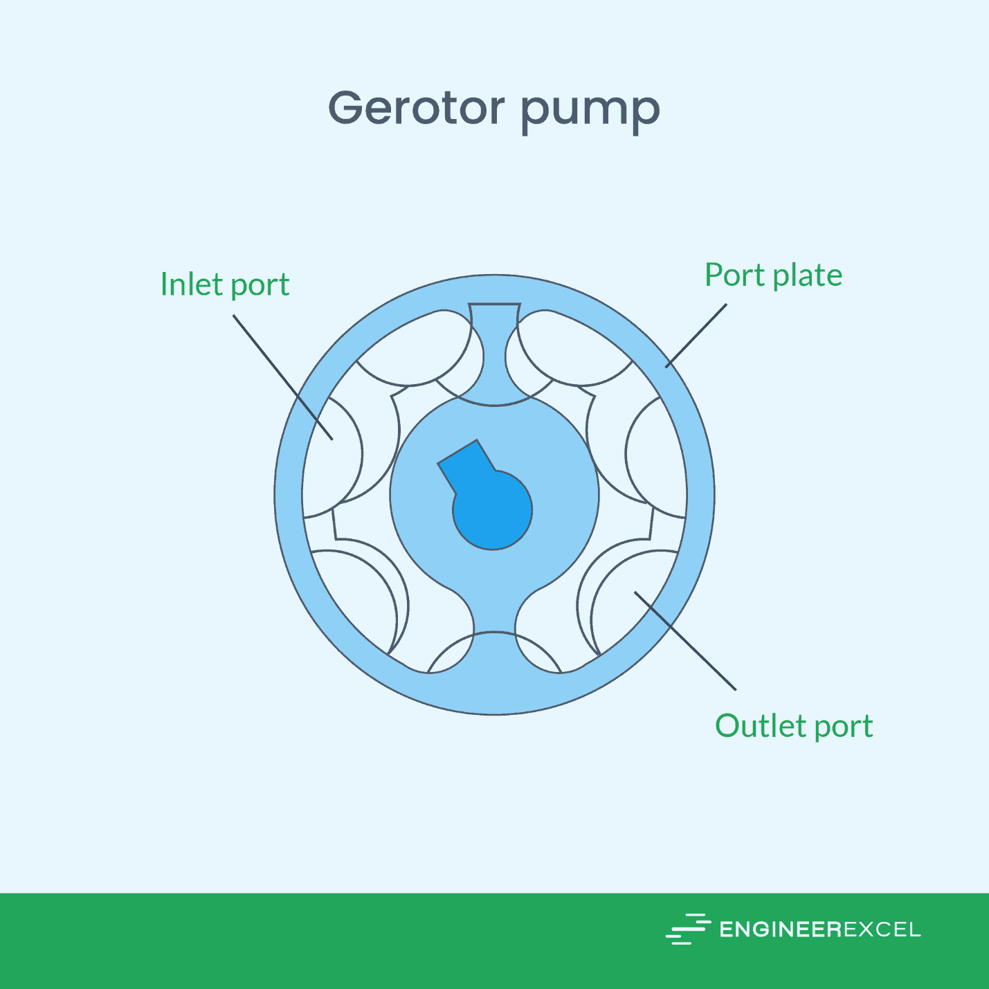
A gerotor motor consists of an outer drive gear with one extra tooth compared to the inner gear. The inner gear is connected to a shaft linked to a load. The torque at the motor shaft is generated by the imbalance in gear area and teeth exposed to hydraulic pressure at the motor inlet.
In general, gear motors have operating limits of 2000 psi for pressure, 2400 rpm for speed, and 150 gpm for flow capacity.
Piston Hydraulic Motors
Piston hydraulic motors use fluid pressure to move pistons back and forth within a cylinder block. This piston movement is then translated into rotary motion, generating mechanical power.
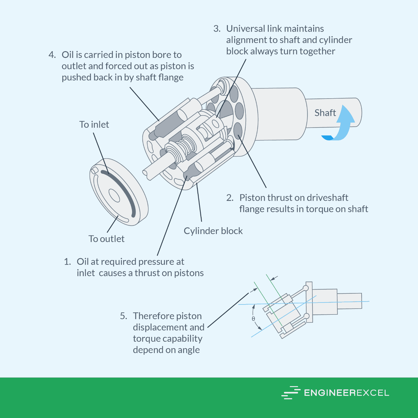
There are two primary configurations for piston motors: swash-plate and bent-axis. These are shown in the figure below.
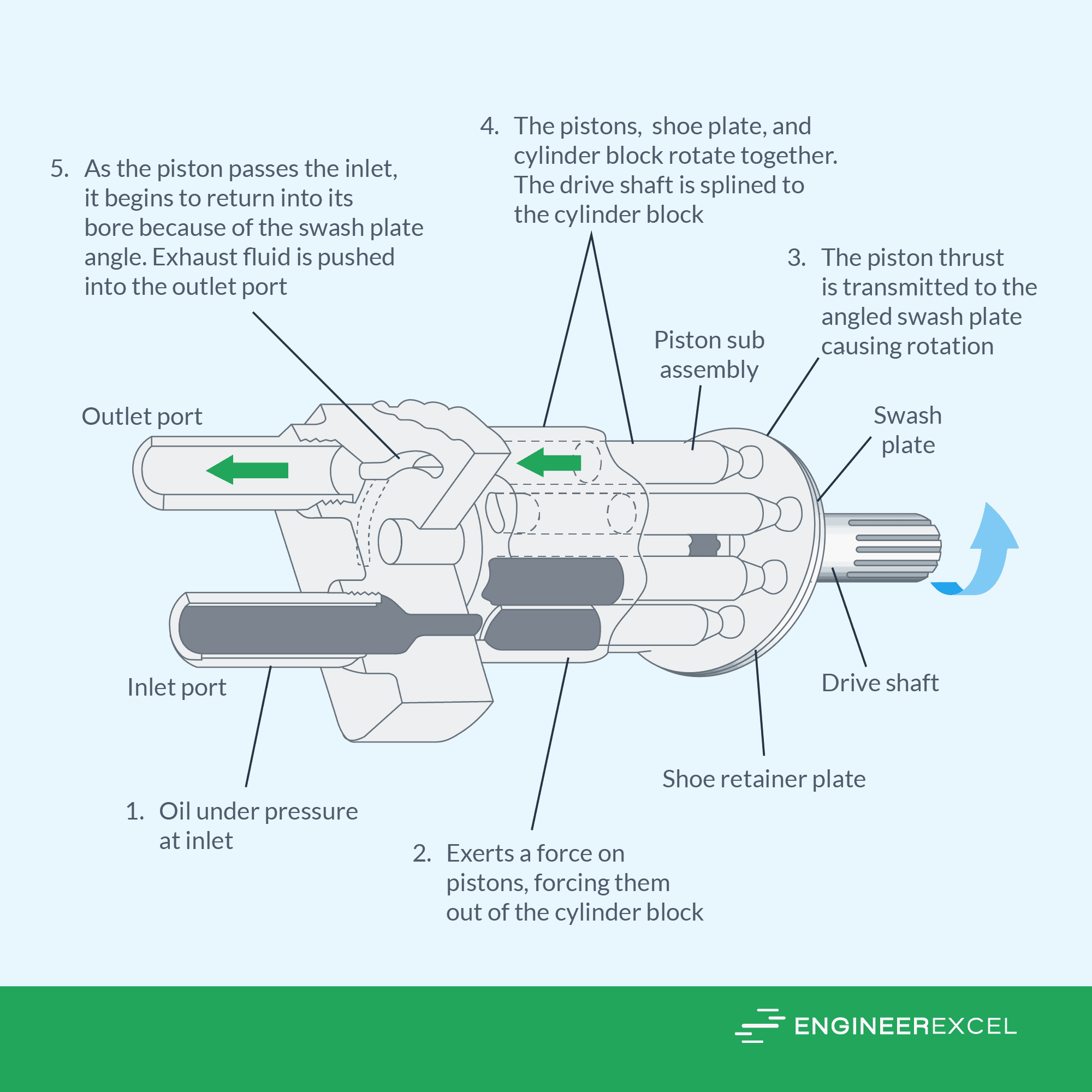
Piston hydraulic motors consist of a cylinder block, pistons, a drive shaft, and a valve system. The cylinder block houses the pistons, which are sealed and slide back and forth within their respective cylinders. The drive shaft is connected to the cylinder block and receives the rotational output.
As the fluid enters the cylinder, the pressure exerts a force on the pistons, forcing them out of the cylinder block. The piston thrust is then transmitted to the angled plate, which causes rotational torque on the shaft. As the piston returns and is pushed back into the cylinder block, exhaust fluid is pushed into the outlet port.
Piston motors are the most efficient of the three primary types of hydraulic motors and are capable of operating at the highest speeds and pressures of up to 12,000 rpm and 5000 psi, respectively. Furthermore, large piston motors can deliver flow capacities of up to 450 gpm.
Hydraulic Motor Calculators
Torque Calculator
The torque generated by a particular motor depends on the system pressure and the motor displacement. In general, higher pressure or larger motor displacement results in increased torque.
Disregarding friction, the theoretical torque of a hydraulic motor can be calculated using the formula:
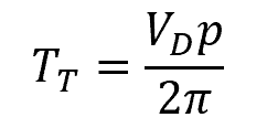
Where:
- TT = theoretical torque [N-m or in-lb]
- VD = displacement [m3/rev or in3/rev]
- p = system pressure [Pa or psi]
The actual torque can be obtained by first measuring the actual power and then dividing it with the motor speed. In metric units, the formula is:
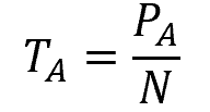
Where:
- TA = actual torque [N-m]
- PA = actual power [W]
- N = motor speed [rad/s]
Taking into account the conversion factor in English units, the formula becomes:
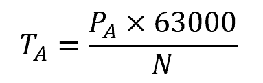
Where:S
- TA = actual torque [in-lb]
- PA = actual power [hp]
- N = motor speed [rpm]
Motor Speed (RPM) and Flow Rate
In metric units, the rotational speed and theoretical flow rate of a motor can be related using the formula:
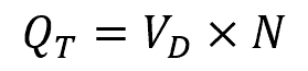
Where:
- QT = theoretical volumetric flow rate [m3/s]
- VD = displacement [m3/rev]
- N = rotational speed [rev/s]
Taking into account the conversion factor in English units, the formula becomes:
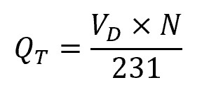
Where:
- QT = theoretical volumetric flow rate [gpm]
- VD = displacement [in3/rev]
- N = rotational speed [rpm]
Motor Power
In metric units, the theoretical power can be calculated using the formula:
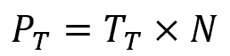
Where:
- PT = theoretical power [W]
- TT = theoretical torque [N-m]
- N = rotational speed [rad/s]
Taking into account the conversion factor in English units, the formula becomes:
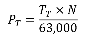
Where:
- PT = theoretical power [hp]
- TT = theoretical torque [in-lb]
- N = rotational speed [rpm]
Motor Efficiency
There are two main components that affect the overall efficiency of the motor: volumetric efficiency and mechanical efficiency. Volumetric efficiency refers to how effectively the motor can move the working fluid into and out of its cylinders or chambers, while mechanical efficiency pertains to how efficiently the motor converts the input energy into mechanical work. It accounts for losses due to friction, heat, and other inefficiencies within the motor’s components.
The volumetric efficiency can be calculated using the formula:
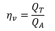
Where:
- ηv = volumetric efficiency [unitless]
- QA = actual volumetric flow rate consumed by the motor [m3/s or gpm]
On the other hand, the mechanical efficiency can be calculated using the formula:
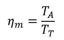
Where:
- ηm = mechanical efficiency [unitless]
- TA and TT = actual and theoretical torque, respectively [N-m or in-lb]
The overall efficiency of the motor can be obtained from these two factors using the formula:
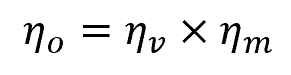
Where:
- ηo = overall efficiency [unitless]