
Cast iron pipe, also referred to as grey cast iron pipe due to its grey fractured appearance, is a type of pipe made from an alloy of iron, carbon, and silicon. It has been used since the seventeenth century in various applications, ranging from water distribution systems to wastewater management.
Cast Iron Pipe Properties and Applications
Before learning about the different cast iron pipe dimensions and standards, it is important to understand their properties and how they have been used historically.
Cast iron pipes are known for their durability and strength. However, because of their high carbon content in the range of 2% to 6.67%, which appears in the lamellar or flaky form, they are relatively harder, more brittle, and more liable to fracture than other types of iron pipes.
For this reason, they are not often used for pressure piping applications, like in the oil and gas industries. In fact, the manufacture of cast iron pipes has already been discontinued in some countries, except for the production of non-pressure drainage pipes.

Elevate Your Engineering With Excel
Advance in Excel with engineering-focused training that equips you with the skills to streamline projects and accelerate your career.
These pipes generally have low ductility and malleability, hence, they cannot be drawn, rolled, or worked at room temperature. If subjected to subsequent heating and quenching, cast iron can fail. However, they can be melted, cast, and machined into complex shapes, making them applicable for use in valve bodies.
These days, cast iron pipes find their primary use in commercial and industrial settings for drain, waste, and vent applications. Because they offer high strength and corrosion resistance, they are also suitable for underground water service and distribution mains. For better protection, it is advisable to coat them both inside and outside the pipe.
Manufacturing Processes for Cast Iron Pipe
The dimensions of cast iron pipes are greatly affected by the manufacturing process used in making them. In general, cast iron pipes can be manufactured using one of three methods: horizontal, vertical, or centrifugal method.
In the horizontal method, molten iron is poured into horizontal molds with core bars, through a ladle designed to draw iron from the bottom and eliminate impurities. Unfortunately, this method often results in uneven metal distribution around the pipe circumference and slag accumulation at the crown, resulting in a much weaker section.
In the vertical pit method, closely the same shape of the mold with a core bar is used except that, this time, it is vertical. Hence, the slag only accumulates at the upper part of the casting and can be easily eliminated by simply cutting off the end of the pipe. Although the vertical pit method produces a cleaner pipe compared to the horizontal method, off-center bores caused by the misplacement of the core are a common occurrence, resulting in an uneven thickness of the pipe.
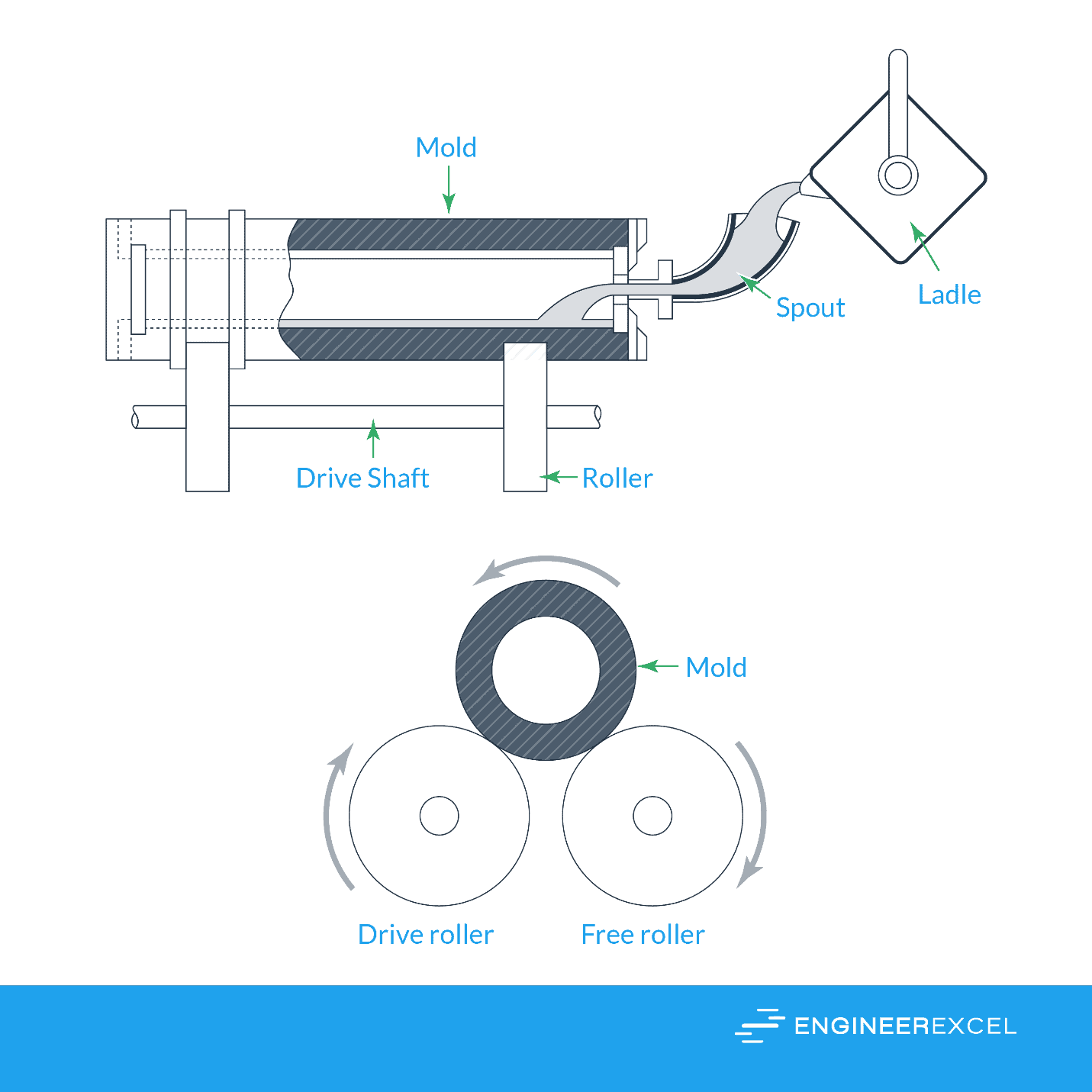
Today, the spun or centrifugal method is the most commonly used method for producing cast iron pipes. It involves using sand-lined molds placed horizontally in centrifugal casting machines, which use rotational motion to distribute molten iron on the walls of the mold to produce pipes within seconds. This method has many advantages including faster production, longer pipes with improved metal qualities, smoother inner surface, and reduced thickness, making the pipes lightweight.
The centrifugal casting setup is shown in the diagram below:
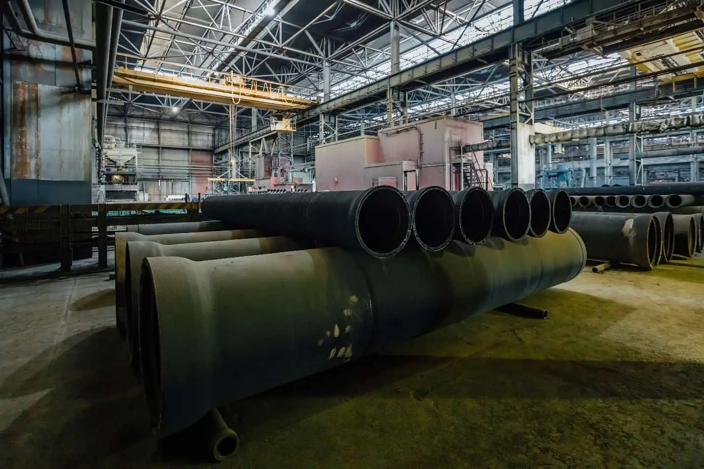
Pipes made through centrifugal casting are available in sizes ranging from 80 mm to 900 mm in diameter and are furnished with protective coatings. The pipes are normally provided in lengths measuring between 3.7 meters to 5.5 meters.
Types of Cast Iron Pipe
Cast iron pipes can be classified into two primary categories: hubless pipes and pipes with a hub (hub and spigot). The difference between the two lies in the way the pipes are joined.
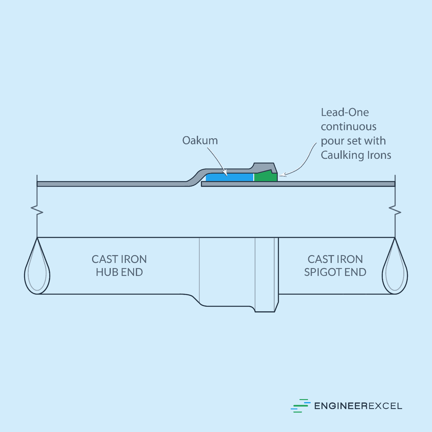
A hub and spigot cast iron pipe has a hub at one end and a spigot (or plain end) at the other. The hub is a bell-shaped end that enables the adjoining pipe’s spigot end to fit inside it, creating a tight and secure connection between the two pipes without the need for additional coupling. It is typically used in larger-diameter pipes and is suitable for higher-pressure applications.
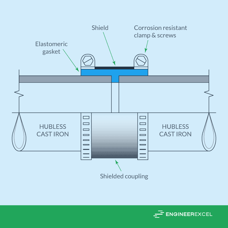
On the other hand, a hubless cast iron pipe does not have a hub at the end of the pipe. Instead, it uses a flexible rubber coupling to connect two pipes, inserted into the pipe’s end and secured in place using clamps. This coupling system simplifies and quickens the installation process compared to a hub and spigot pipe.
Cast Iron Pipe Dimensions and Standards
The first set of specifications developed to standardize the size and dimensions of cast iron pipes is the British Standard BS 78-2:1965, which provided specifications for vertically cast iron spigot and socket pipes and fittings. However, this standard has been obsolete since 1988.
Today, manufacturers worldwide follow various standards for both hubless and with-hub cast iron pipes including standards developed by the American Society for Testing and Materials (ASTM), British Standards (BS), Cast Iron Soil Pipe Institute (CISPI), Canadian Standards Association (CSA), and American National Standards Institute (ANSI), among others.
The dimensions of some of the most common series of cast iron pipes are shown in the tables below.
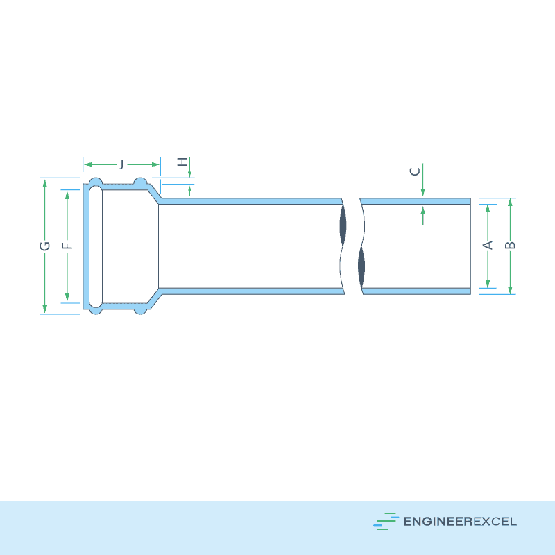
Hubless Cast Iron Pipe conforming to ASTM A888 and CISPI 301
Dimensions of Hubless Cast Iron Pipe conforming to CSA B70
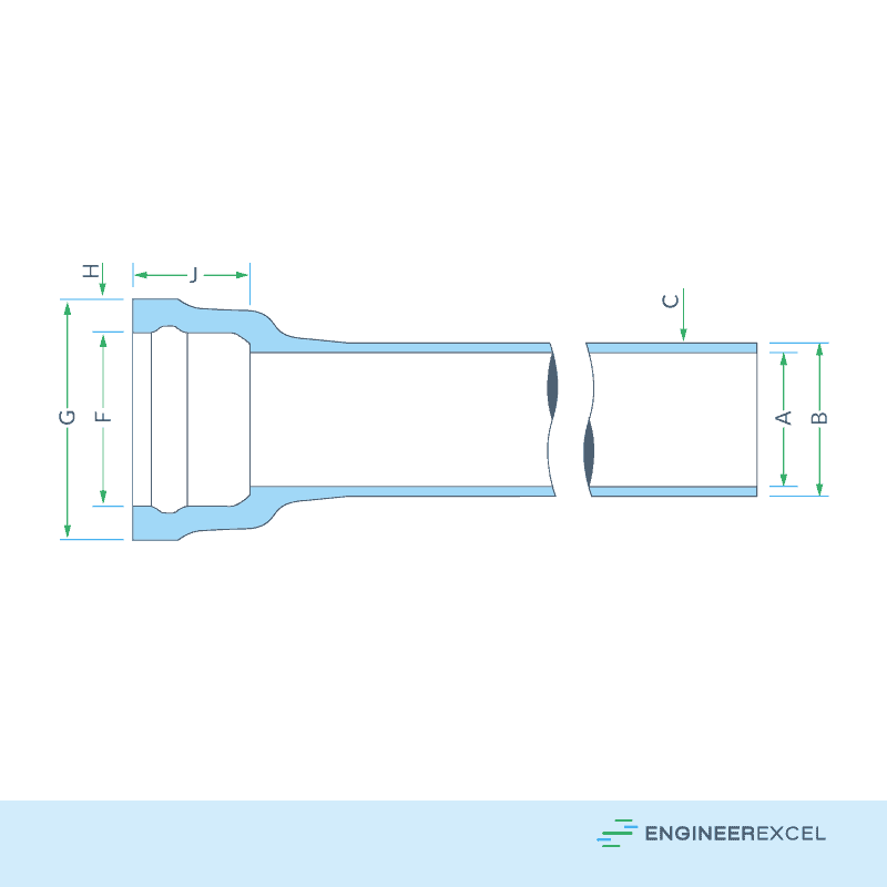
Dimensions of Single Spigot and Socket Cast Iron Pipe conforming to BS416
Dimensions of Single Spigot and Socket Cast Iron Pipe with Flexible Rubber Ring Joint Conforming to BS437
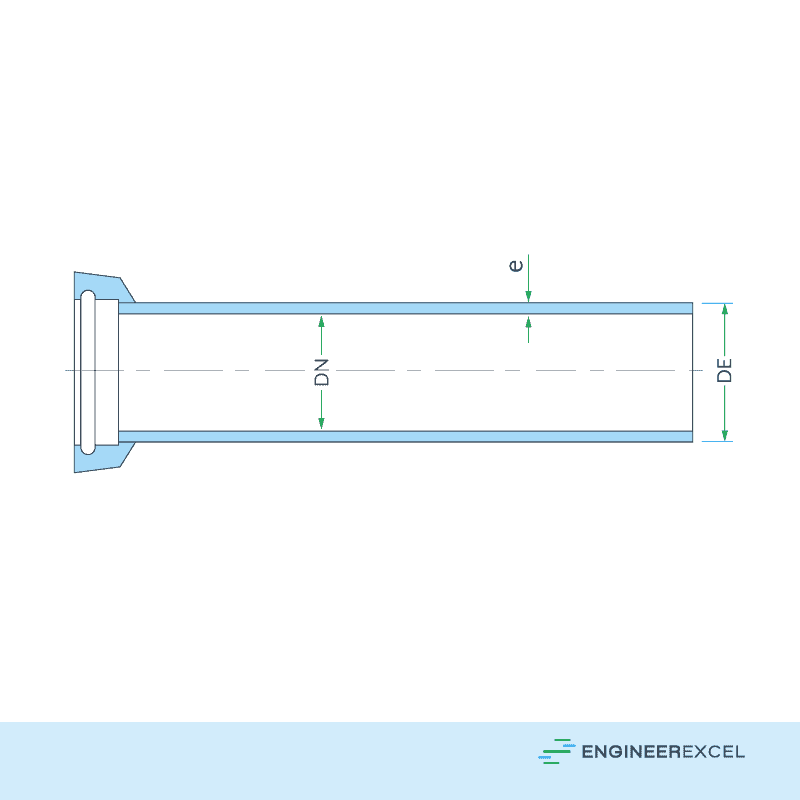
Dimensions of Single Spigot Cast Iron Drain Pipe Conforming to BS4622
ANSI and AWWA Cast Iron Pipe Dimensions
Some standards, like ANSI and AWWA, classify cast iron pipes according to the hydrostatic working pressure that the pipes can handle. For example, a Class 50 pipe can handle 50 psi of working pressure with a safety factor of 2.0.
For centrifugally cast pipe, the relevant standards are ANSI A21.6, ANSI A21.8, AWWA C106, and AWWA C108. Pit cast pipe standards are ANSI A21.2 and AWWA C102.
The dimensions of cast iron pipes for classes 50, 100, 150, 200, and 250 conforming to ANSI and AWWA standards are shown in the tables below.