
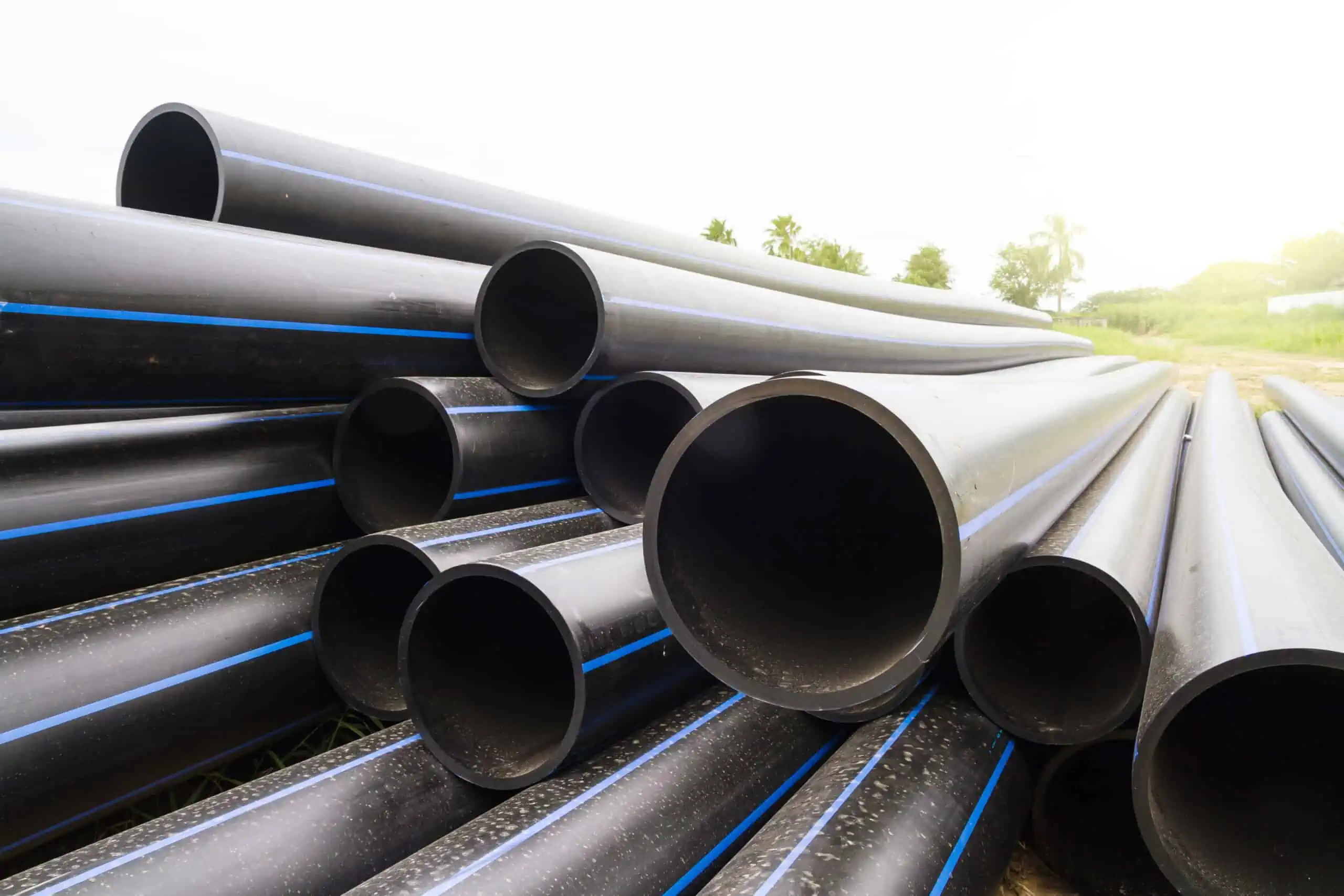
Polyethylene (PE) pipes are widely used for transporting fluids at low and medium pressure in various industries such as water and sewerage due to their versatility, durability, ease of installation, resistance to corrosion, competitive cost, and ability to be installed completely leak free. To ensure the quality and reliability of PE pipes, standards and specifications have been established by organizations like the American Society for Testing and Materials (ASTM). One such standard is ASTM D3035, which will be the focus of this article.
Understanding ASTM D3035
ASTM D3035 is a standard specification established by the American Society for Testing and Materials (ASTM) that sets the minimum requirements and test methods for PE pipes used in water supply, industrial, and general-purpose applications. The specification covers PE pipes made from high-density polyethylene (HDPE) or medium-density polyethylene (MDPE) materials that are classified according to their pressure rating (PR) and dimension ratio (DR) based on outside diameter.
The specification encompasses several aspects, including material requirements for PE compounds, a nomenclature system for plastic pipes, dimensional and tolerance requirements for outside diameters and wall thicknesses, and requirements and test methods for burst pressure, apparent tensile strength, sustained pressure, and pipe pressure ratings.
It is worth noting that this article is based on ASTM D3035-14, which covers nominal pipe sizes ranging from IPS ½ to 24 inches. However, in ASTM D3035-21, changes have been implemented to address the issue of duplicate sizes found in other ASTM specifications. As a result, the updated version only encompasses nominal pipe sizes from IPS 1/2 to 3 inches.

Elevate Your Engineering With Excel
Advance in Excel with engineering-focused training that equips you with the skills to streamline projects and accelerate your career.
The standard units used in this specification are inch-pound. Nevertheless, SI units are provided as supplementary information.
Pipe Dimension Ratio
ASTM D3035 encompasses PE pipes of different thermoplastic pipe dimension ratios (DR), including DR 7, DR 9, DR 9.3, DR 11, DR 13.5, DR 15.5, DR 17, DR 21, DR 26, and DR 32.5. The dimension ratio is determined using the following formula:
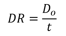
Where:
- DR = thermoplastic pipe dimension ratio [unitless]
- Do = average outside diameter [in or mm]
- t = minimum wall thickness [in or mm]
Pressure Rating Of PE Pipes
Pipe pressure rating refers to the maximum allowable pressure that a pipe can safely withstand without experiencing failure or leakage. The pressure rating can be related to the dimension ratio and hydrostatic design stress using the following formula:
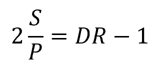
Where:
- P = pressure rating [psi or MPa]
- S = hydrostatic design stress for water at 73°F or 23°C [psi or MPa]
For a given PE pipe material and dimension ratio, the pressure rating remains consistent across all nominal pipe sizes, as shown in the table below. These pressure ratings are determined using water at 73°F or 23°C and are generally suitable for use at service temperatures up to 80°F or 27°C.
Material Requirements For PE Pipes
The table below shows the material requirements for the different polyethylene compound materials used in PE pipes.
These requirements ensure the structural integrity, processability, and durability of the pipes. The specified properties include Hydrostatic Design Basis (HDB), Hydrostatic Design Stress (HDS), melt flow rate, density, Slow Crack Growth (SCG) resistance, as well as color and UV stabilizer codes. These properties are evaluated in accordance with ASTM D2837, ASTM D1238, and ASTM D3350, respectively.
In general, PE pipes should be homogeneous throughout, devoid of any visible cracks, holes, foreign inclusions, or defects. Additionally, they must exhibit consistency in terms of color, opacity, density, and other physical characteristics.
Dimensional Requirements for PE Pipes
In terms of dimensions, the table below shows the required outside diameter measurements and tolerance specifications for PE pipes at different nominal pipe sizes.
In addition, the table below shows the minimum required wall thicknesses and tolerance specifications of PE pipes at different nominal pipe sizes and dimension ratios.
Pipe measurements shall be conducted in accordance to Test Method D2122. If the outside diameter and wall thickness measurements are not listed in the tables above, the tolerances shall be determined based on the closest listed measurement, using the same percentage. For wall thickness, a tolerance range of up to 12% is acceptable.
Burst Pressure Requirements For PE Pipes
Burst pressure refers to the maximum internal pressure that a pipe can withstand before it ruptures or fails.
The table below shows the minimum burst pressure requirements for PE pipe materials across different dimension ratios. When testing for burst pressure, the specimen should be tested in accordance to Test Method D1599 and the failure mode observed shall be ductile.
Apparent Tensile Strength Requirements For PE Pipes
Apparent tensile strength refers to the ability of a pipe material to resist tensile forces or stretching. It is a measure of the maximum stress or force that the pipe can withstand before it ruptures or fails in tension.
The following table shows the apparent tensile strength requirements for the different PE pipe materials. This shall be tested on at least 5 ring specimens cut from the pipes, with testing conducted in accordance to Test Method D2290. The observed failure mode should be ductile.
Sustained Pressure Requirements For PE Pipes
PE pipes are subjected to sustained pressure test in order to verify their integrity and strength by subjecting them to a constant pressure for a specific duration. The purpose of this test is to ensure that the pipes can withstand the anticipated operating pressure without leaking or failing.
For pipes other than PE 1404, the sustained pressure test must be performed on at least 3 representative specimens at elevated temperatures under the specified pressure hoop stress and time conditions indicated in the table below. For PE pipes used in production facilities, testing shall be conducted twice annually in accordance with Test Method D1598 using water as the internal test medium.
On the other hand, for PE 1404, the sustained pressure test must be performed at both ambient and elevated temperatures as indicated in the table below. Acceptable results are defined as non-failure within the minimum average test time or brittle failure occurring after the minimum average test time has elapsed.
For more accurate details about the test methods, it is best to refer to ASTM D3035 directly.
PE Pipe Marking
PE pipes conforming to this standard specification must be clearly marked with the following information at intervals of no more than 5 feet: nominal pipe size, designation code indicating the type of PE material used, pipe dimension ratio, water pressure rating in psi, “ASTM D3035,” and manufacturer’s name or trademark. For pipes intended for potable water, they must also bear the seal of an accredited laboratory.
In terms of color coding, blue should be used to indicate potable water, green for sewer, and purple for reclaimed water. This specification prohibits markings that identify gas, communications, or electrical usage.
ASTM D3035 vs ASTM F714
Both ASTM D3035 and ASTM F714 standards are used for PE plastic pipes that are pressure-rated for water and with pipe dimension ratios based on outside diameter. However, despite having almost the same title, there are notable differences between the two.
Specification D3035 specifically focuses on outside diameters and tolerances using the IPS (Iron Pipe Size) Sizing System. On the other hand, Specification F714 encompasses specifications for multiple sizing systems, including IPS, DIPS (Ductile Iron Pipe Size), and ISO. This makes F714 more comprehensive in terms of sizing options.
Moreover, D3035 and F714 differ in the range of pipe sizes they cover. D3035 provides specifications for IPS nominal sizes ranging from ½ inch to 3 inches. In contrast, F714 extends its specifications to IPS nominal sizes from 3 inches to 54 inches. Additionally, F714 includes specifications for DIPS nominal sizes ranging from 3 inches to 48 inches and ISO nominal sizes ranging from 90 mm to 1600 mm.
Both D3035 and F714 comply with the requirements specified in ASTM D3350, which pertains to the classification and properties for polyethylene pipe materials.