
Bolted joints are one of the most widely used methods in construction and manufacturing industries to hold multiple mechanical components together. They involve the use of a threaded joint and nut which are tightened in order to compress holed components together through which the bolt passes.
This article focuses on bolt preload— one of the crucial factors that needs to be considered in the design and installation of bolted joints.
Bolt Preload Explained
Aside from the number, size, and location of bolts, determining the appropriate preload for a bolt is an important factor that needs to be considered in the design of a bolted joint in order to create a secure and reliable connection.
Bolt preload, or clamp load, is basically the pre-applied force that compresses the bolted components together. It is created by tightening the bolt screw against a nut during installation.

Elevate Your Engineering With Excel
Advance in Excel with engineering-focused training that equips you with the skills to streamline projects and accelerate your career.
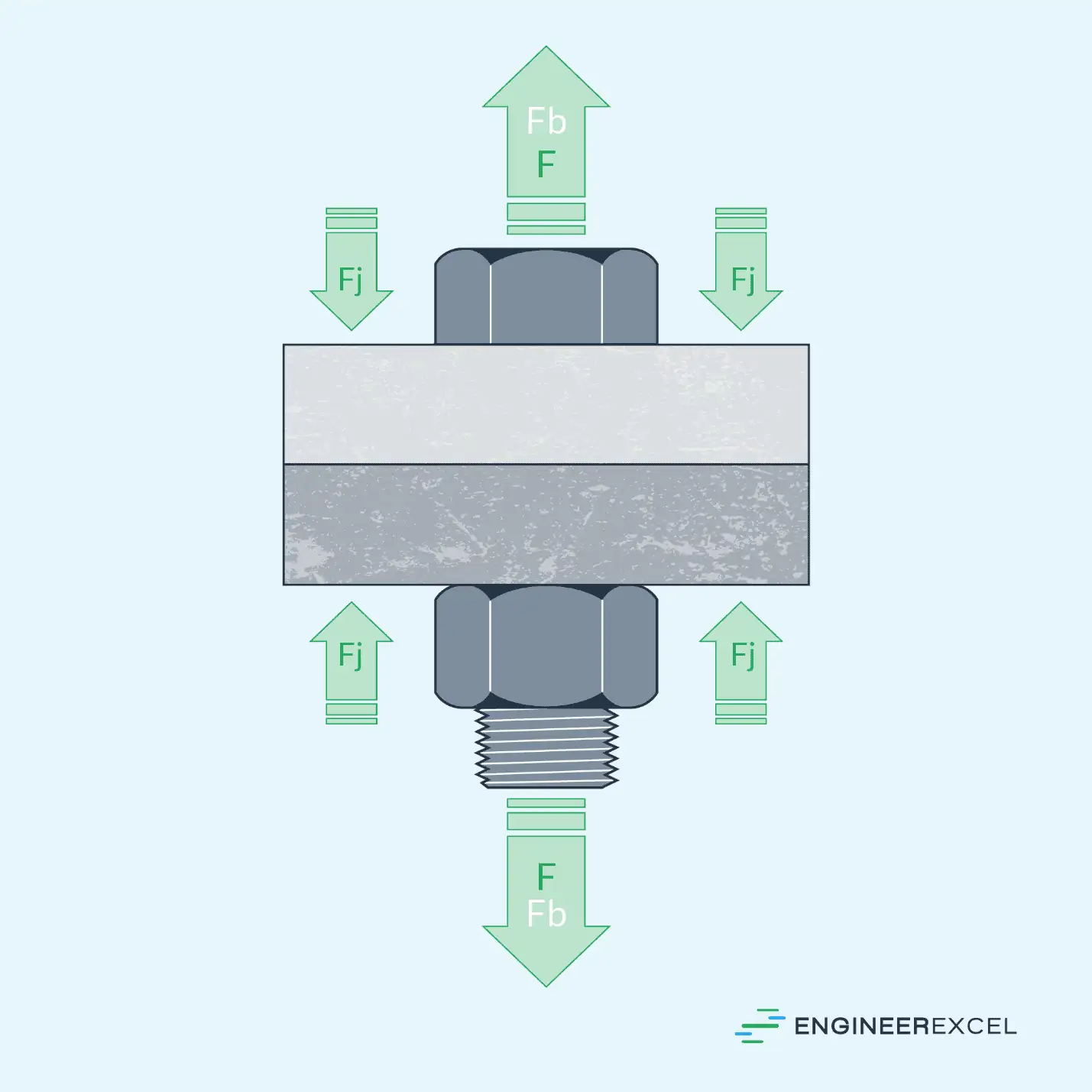
The preload acts as a compressive force on the joint and as a tensile force on the bolt, causing the joint to compress and the bolt to stretch axially, as shown in the diagram below.
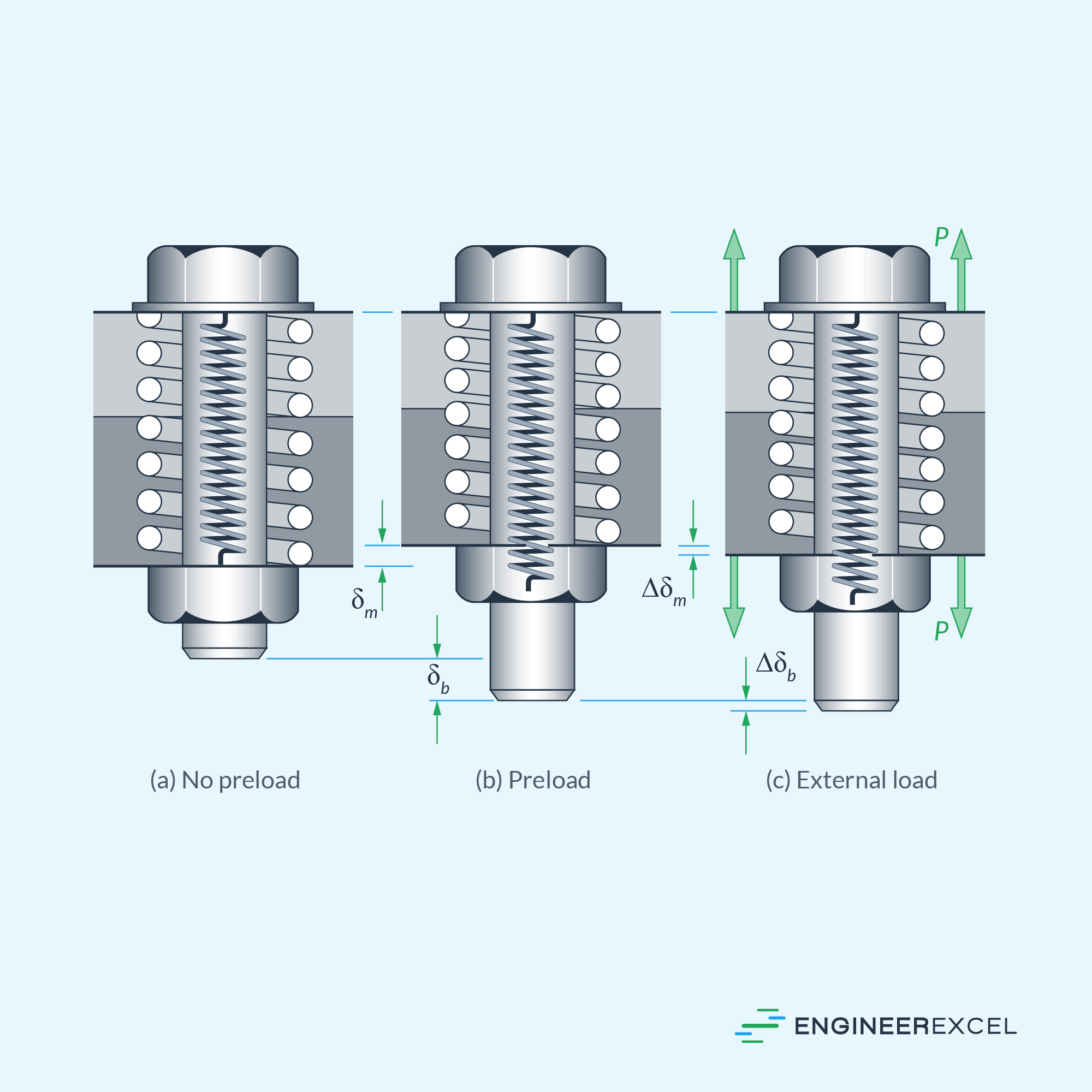
When an external tensile force is applied on the joint, the preload counteracts the force, holding the joint in place and preventing separation or any kind of relative movement between the bolted components. Hence, the magnitude of the preload is designed such that it is never overcome by any external forces acting to separate the joint.
In essence, applying bolt preload also enhances the strength of the bolt. This is because, when an external tensile force is applied to a tightened joint, the force is distributed through the material such that the bolt only bears a fraction of the load. This fraction depends upon the ratio of stiffnesses of the bolt to the joint material.
However, when the combined external forces applied exceed the preload, the joint separates, placing the entire weight burden on the bolt, which can potentially result in damage. Hence, it is important to ensure that the preload is sufficiently applied to ensure a secure and safe connection.
Bolt Preload Calculation
The determination of the necessary preload relies on several factors, including the magnitude and direction of forces expected to act on the joint, as well as potential preload losses during installation and operation.
A common guideline, as suggested by the Machinery’s Handbook, is to assume 75% of the proof strength for removable fasteners and 90% for permanent fasteners. However, for a more precise determination of the preload requirement, it is essential to consider the combined effect of all external forces and account for any losses that may affect the overall tensile force the preload must overcome. This is graphically shown in the chart below.
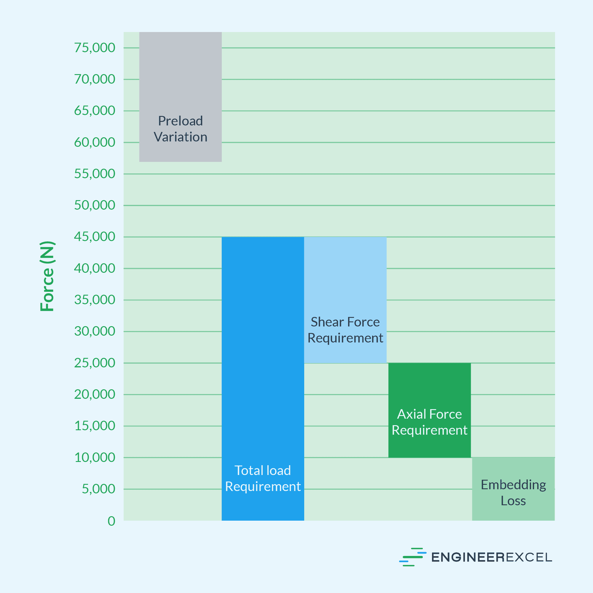
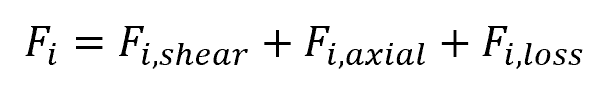
In general, bolts experience two types of external forces: axial and shear. Based on the chart, the total bolt preload requirement can be conservatively calculated using the formula:
Where:
- Fi = total bolt preload requirement [N]
- Fi,shear = contribution of external shear forces on the required preload [N]
- Fi,axial = contribution of external tensile axial forces on the required preload [N]
- Fi,loss = possible preload losses [N]
Compressive Axial Load
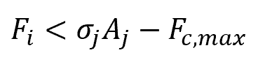
When the external axial force applied is compressive, it combines with the compressive preload experienced by the joint. Hence, it is important to ensure that the magnitude of the preload is less than the yield strength of the joint minus the maximum compressive external load to avoid damaging the joined components.
This is shown in the equation:
Where:
- Fc,max = maximum externally applied compressive axial load [N]
- σj = yield strength of the joint [N/m2]
- Aj = cross-sectional area of the joint being compressed [m2]
Tensile Axial Load
When the external axial force applied is tensile, the load is distributed between the joint and the bolt materials. A portion of the load decreases the compressive load experienced by the joint, while another portion increases the tensile load experienced by the bolt. The specific distribution of the load depends on the stiffness of both the joint and bolt materials.
Consequently, the contribution of the maximum external tensile axial force on the required preload can be calculated using the formula:
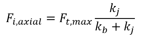
Where:
- Fc,max = maximum externally applied tensile axial load [N]
- kj and kb = stiffness of the joint and bolt materials, respectively [N/m]
However, in practice, it is common to adopt a conservative approach by assuming that the entire applied tensile axial load decreases the clamp force exerted on the joint interface.
Shear Load
Shear load occurs when the applied force acts perpendicular to the axis of the bolt. The impact of shear load on the bolt preload requirement depends on the type of joint configuration employed.
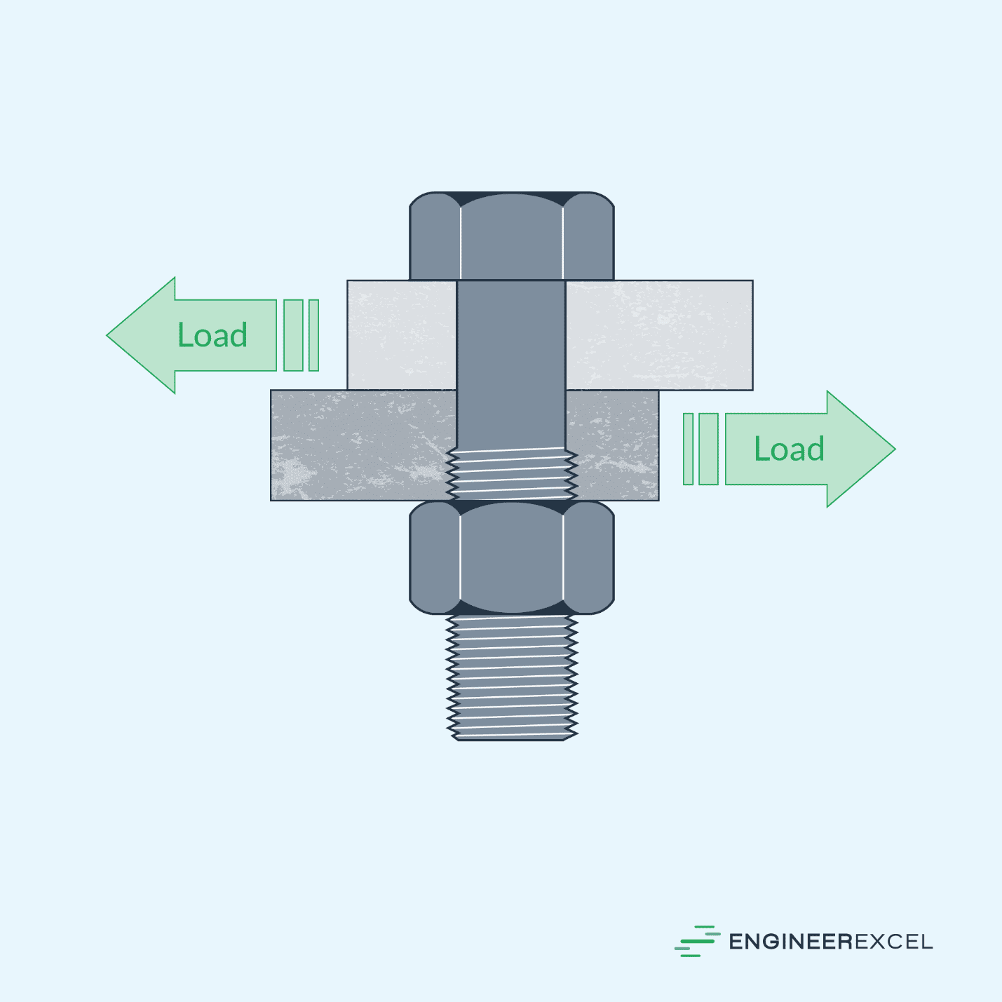
In bearing-type joints, the bolt acts as a pin, enabling sliding between the joint members. The primary mechanism to prevent further slippage is through bearing pressure. In such cases, the significance of preload during assembly is insignificant, as long as the fastener remains securely fastened.
On the other hand, in friction-type joints, the preload plays a vital role in withstanding shear loading by inducing friction force that prevent slippage between the joint members. As long as the friction force is greater than the shear load, the bolts themselves do not directly bear any shear loads. Nonetheless, they must be adequately preloaded to generate the necessary friction.
This preload value can be calculated by dividing the shear force by the coefficient of friction between the joint surfaces. Consequently, the contribution of the maximum external shear force on the required preload can be calculated using the formula:
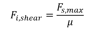
Where:
- Fs,max = maximum externally applied shear load [N]
- μ = coefficient of friction between the joint surfaces [unitless]
Preload Loss
In most preloaded joints, there is typically a degree of preload loss due to factors such as plastic deformation under the nut face, joint faces, and threads, which results in the flattening of surface roughness. Preload loss can range from around 2% to 10% of the actual preload level in the bolt.
For joints where there is metal-to-metal contact across their entire thickness, an assumed preload loss of 5% is commonly used. However, for joints involving nonmetallic materials, the specific preload loss needs to be determined through application-specific testing.
Bolt Preload Measurement and Application Methods
There are various methods that can be used to achieve the desired preload, such as applying a specific torque, measuring bolt extension, conducting ultrasonic testing, or applying a specific degree of relative rotation between the bolt and nut, among others. However, each method has its own uncertainties. For example, applying the same torque may not consistently produce the exact preload due to variations in tolerances, coefficient of friction, and other factors.
The accuracy of some of the most common bolt preload application methods are shown in the table below.
This also means that each tightening method has both a maximum anticipated preload and a minimum preload. To ensure a secure connection, the tightening method should be chosen based on its minimum preload value.
The gap between the total preload requirement and the minimum preload value defines the factor of safety for the joint. There are no specific design codes dictating the factor of safety, hence, it ultimately depends on engineering judgment.
If the forces are accurately known or if product testing will be conducted, a smaller gap can be acceptable. However, if the forces are uncertain and failure consequences are severe, it is safer to assume a larger gap. It is important to note that a generous factor of safety may require a larger bolt size or higher-strength bolt, resulting in a more expensive assembly.
Preload vs Torque
Using a calibrated wrench to apply torque is a common method for tightening bolted joints. However, it is important to note that torque is only an indirect indication of the applied tension. Hence, the resulting tension may vary from the intended preload value.
In many cases, a linear relationship exists between the applied torque and the resulting tension. The equation for torque, shown below, applies to such situations.
Where:
- T = tightening torque [N-m]
- K = nut factor [unitless]
- d = bolt diameter [m]
The nut factor accounts for various factors that influence friction during the tightening process. These factors include the effect of variations in thread shape, thread friction between the bolt and nut threads, and friction between the nut and the surface it rotates on.
Although published tables for the nut factor exist, they often differ due to various factors, such as the types of materials involved, surface finish, use of washers, tightening speed, type of lubricant, amount of lubricant, and more. Moreover, real-world complications like dirt in tapped holes, damaged threads, and hole misalignment can absorb significant input torque, reducing the effective energy that actually becomes preload.
Nevertheless, the table below shows the approximate nut factors for some of the most common bolt types.