Depending on the material and the process used to manufacture the pipe, commercial pipes have different levels of roughness which affects the behavior of the fluid flowing through the pipe, particularly the pressure loss caused by friction.

In general, as the roughness increases, the frictional loss also increases. Hence, when designing a piping system, it is important to consider pipe roughness to ensure accurate pressure loss calculations and select the appropriate size of pumps and motors to run the system.

Pipe Roughness Measurement
Pipe roughness is a measure of irregularity or unevenness of a pipe’s internal wall surface. In more technical terms, it can be defined as any deviation of its actual internal surface from an ideal datum level.

Elevate Your Engineering With Excel
Advance in Excel with engineering-focused training that equips you with the skills to streamline projects and accelerate your career.
There are various methods to measure pipe roughness. Some use highly sensitive profiling instruments to detect height deviations in the nanometer range, while some estimate pipe roughness from actual flow and pressure measurements by relating it to the friction factor using the Darcy-Weisbach equation.

However, it is typically the pipe manufacturers who declare these values. In general, manufacturers define pipe roughness in either absolute or relative values.
Absolute Pipe Roughness, ε
The absolute pipe roughness coefficient is solely dependent on the material finish and is a measure of the surface’s average height deviation in comparison to a perfectly smooth finish. It is typically specified in mm or inches.
The absolute pipe roughness, denoted as ε, of some of the most common pipe materials are listed below.
Note that since the material finish of commercial pipes varies widely depending on the manufacturer, there may be errors in these values relative to the actual conditions. A typical tolerance for published roughness values may be assumed to be between ±30% to ±50%.
Relative Pipe Roughness
The relative pipe roughness, also known as the roughness factor, is defined as the ratio between the absolute pipe roughness and the hydraulic diameter of the pipe. Unlike absolute pipe roughness, it is dimensionless and is dependent on both the material finish and pipe size.
It can be calculated using the formula:

Where:
- ε = absolute pipe roughness coefficient [millimeters or inches]
- dh = hydraulic diameter of the pipe [millimeters or inches]
Ultimately, it is the relative pipe roughness that affects the friction factor and, consequently, the frictional head loss in a piping system.
Welded Steel Pipe Roughness
As an example, a 50-mm welded steel pipe with an absolute roughness of 0.060 mm will result in a relative pipe roughness equal to 0.00006, as shown in the calculation below.

PVC Pipe Roughness
Another example, a 100-mm PVC pipe with an absolute roughness coefficient of 0.002 mm will result in a relative pipe roughness equal to 0.00002, as shown in the calculation below.

Effect Of Pipe Roughness On Fluid Flow And Pressure Drop
Pipe roughness plays a significant factor in the flow of fluid inside a pipe. It affects the value of the friction factor which, consequently, influences the pressure drop caused by friction in the piping system.

However, it should be noted that pipe roughness does not affect the value of the friction factor for hydraulically smooth or laminar flows, which occur at Reynolds numbers below 2000. To be more accurate, a hydraulically smooth flow corresponds to the following condition:

Where:
- Re = Reynolds number of the fluid flow [unitless]
- f = friction factor [unitless]
On the other hand, for hydraulically rough or turbulent flows, a hydraulically rough flow corresponds to the following condition:

For the transitional region between the laminar and turbulent conditions, with Reynolds numbers between 1100 to 2200, the pipe roughness affects the friction factor according to the Colebrook-White equation as follows:

Since the friction factor is implicitly and nonlinearly dependent on the pipe roughness and the Reynolds number, the Colebrook-White equation is normally solved using iterative numerical methods. However, using iterative methods to find the friction factor can be tedious. To make the process easier, the solutions have been graphically represented on a chart called the Moody Diagram, as shown below.
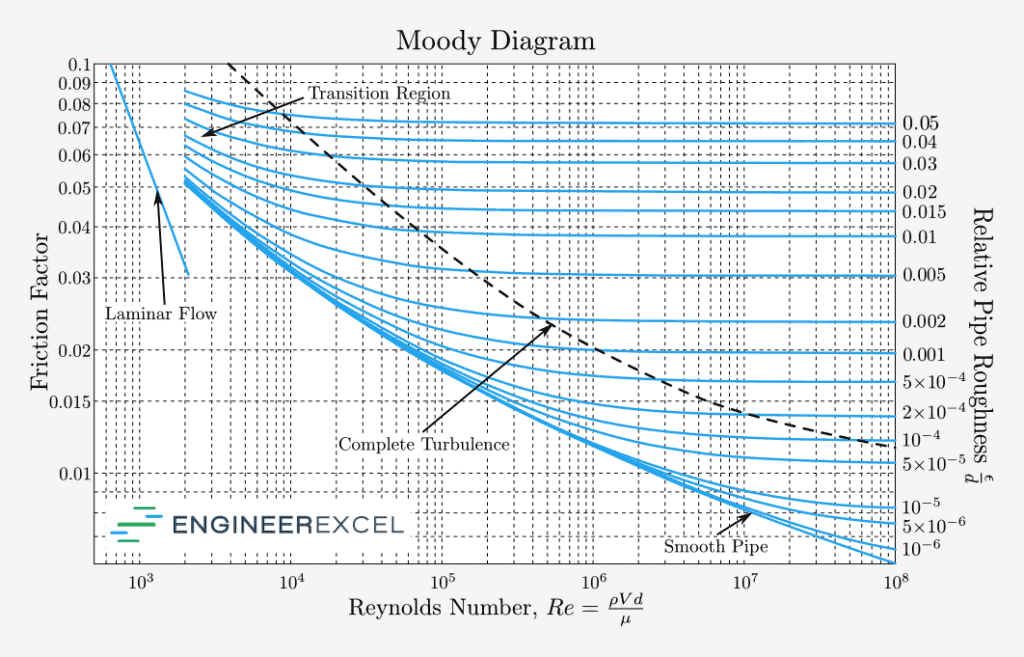
The Moody Diagram relates the friction factor, the Reynolds number, and the relative pipe roughness for fully-developed flow in a circular pipe. A fully-developed flow means that the velocity profile is consistent along the flow direction.
Hence, the Moody Diagram can be used to estimate the friction factor for a non-laminar flow graphically. However, just like any graphical method, this is prone to errors. Although it can be used for teaching purposes and for rough preliminary calculations, it is discouraged to be used for applications requiring accurate calculations.
When designing highly sensitive piping systems, it is still more appropriate to use iterative numerical calculations or a more accurate approximation like the Swamee–Jain approximation, the Haaland approximation, or the Lambert W-Function.

It should also be noted that although the pipe roughness is normally only determined during the pipeline installation, it is a good practice to periodically recheck its value and recalibrate the piping system accordingly. This is because the internal walls of pipes can be eroded or coated with mineral particles with continuous operation, hence, the pipe roughness is expected to change over time.
