
As an object moves through air, it will be subject to an air resistance force. This force is related to a number of parameters specific to a scenario, with the object’s velocity having the largest impact on the air resistance.
Air Resistance Calculator
Calculating air resistance
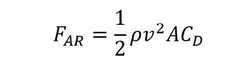
The force imparted on an object moving through the air can be calculated using the following formula:

Elevate Your Engineering With Excel
Advance in Excel with engineering-focused training that equips you with the skills to streamline projects and accelerate your career.
where:
- ρ is the density of the air, with units of lbm/ft3
- v is the velocity the object is moving, with units of ft/s
- A is the area of the object exposed to the airflow, with units of ft2
- CD is the drag coefficient, which is a dimensionless value
The density of air will vary with altitude, generally decreasing as altitude increases. The lower air density at higher altitude is one reason why aircraft fly at altitudes above 30,000 ft. Typically, the value for air density will be determined using a look-up-table.

The area exposed to the airflow may be different than simply the cross-sectional area of the object. The size and shape of an object are often combined and define the aerodynamics of the object. For example, a flat plate perpendicular to the flow of air is less aerodynamic than a cone, so the flat plate will experience more air resistance. Making an object more aerodynamic is a matter of reducing the area exposed to the airflow.
The drag coefficient is specific for a given scenario, and will include various other parameters related to the aerodynamics of the object. The value of this coefficient will have been determined through extensive experimentation over numerous scenarios, and will be determined via a table or chart.
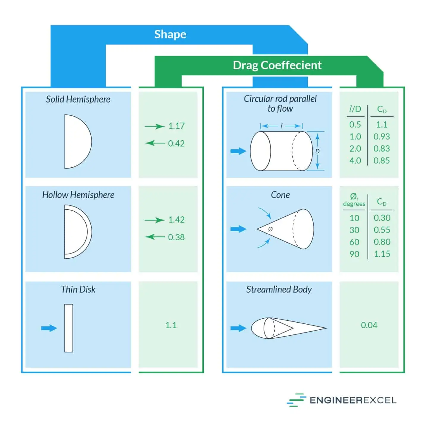
Examples of drag coefficients for different bodies are shown in the following image:
As stated, the velocity of an object has the largest impact on the air resistance it experiences. From the above equation, the air resistance will increase exponentially as the velocity increases. This means that for an object to travel at a higher velocity, it is necessary to minimize the area and drag coefficient as much as possible by improving the aerodynamics, while minimizing the air density by operating at a higher altitude.
Air Resistance Calculation Example
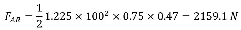
As an example, assume a sphere is moving through the air at sea level with a velocity of 100 m/s. The area of the sphere exposed to the airflow is 0.75 m2. The drag coefficient of a sphere is 0.47 and the air density at sea level is 1.225 kg/m3. The air resistance force is calculated as follows:
Free fall air resistance
For an object in free fall through the air, gravity will cause the object to accelerate. As the velocity of the object increases, the air resistance force will increase exponentially until it is equal to the force exerted by gravity. At this point, the forces acting on the object are equal and opposite, and the object will no longer accelerate.

This velocity is called the terminal velocity. The terminal velocity is the maximum velocity that an object in free fall will achieve.
The force acting on the object due to gravity can be calculated by the following equation:
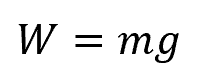
where:
- W is the weight of the object, with units of N
- m is the mass of the object, with units of kg
- g is the gravitational acceleration, which is equal to 9.81 m/s2
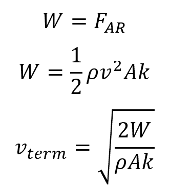
Setting the weight equal to the air resistance, the terminal velocity can be determined as follows:
Minimizing air resistance
Air resistance can induce a large force on an object, but reducing air resistance to achieve optimum operation, generally in the form of increased velocity, is possible. Considering the factors involved in calculating the air resistance, various approaches can be applied.
Aerodynamics
The aerodynamics of an object are related to its size and shape, and can be expressed by both the area A and drag coefficient CD. The shape of an aircraft or rocket has been optimized using computational fluid dynamics (CFD) and previous engineering experience, and similar approaches are used in the design of vehicles. Reducing the area of an object exposed to the air flow affects both air resistance parameters, with CFD and advanced numerical calculations being employed to determine the value of CD for optimized shapes with minimum exposed area.

Air Density
Reducing the air density that an object is operating in will minimize the resistance. However, unlike the aerodynamics of the object, the air density is not something that can be controlled through engineering. To reduce the impact of air density, aircraft are designed to fly at higher altitudes, and rockets may be designed to increase thrust after passing through the denser atmosphere closer to the Earth’s surface. As an example of the impact the air density has on air resistance, the density at sea level is 0.0765 lbm/ft3 and 0.0238 lbm/ft3 at 35,000 ft, representing a more than three-times decrease in air resistance.
Compressible flow
The above calculations are applicable only to incompressible laminar flow. In actual applications, the flow of the air may be compressible and turbulent. Compressible flow will change the density of the air as the velocity increases. Turbulent flow will induce additional air resistance on an object, much of which is accounted for in the drag coefficient, but compressible turbulent flow introduces additional complications. The use of CFD enables modeling compressible flow for determining air resistance.